Mica Sheets
& Boards

Choose mica insulation around the component, not just the material name.

Mica Sheet Supplier for Industrial Insulation

Sheet Materials and Drawing-Based Insulation Components

Mica sheets and boards provide a starting point for components that need electrical separation, resistance to heat, or both. Their useful shape may be a simple flat barrier, a slotted heater support, a fitted insulating layer or a substantial blank for machining. These duties should not be grouped under a single universal grade. A part that follows a curved surface needs a different construction from a plate that holds a defined position in an assembly. Begin by identifying the surfaces being separated, the available installation space and the way the insulation will be supported throughout service. Include the condition of cut edges and any restrictions imposed by the surrounding components.

Our product range separates five routes: rigid muscovite sheets, rigid phlogopite sheets, flexible mica sheets, thick mica plates and commutator mica plates. Muscovite and phlogopite identify mineral families; rigid and flexible describe the behaviour of a manufactured construction. Thickness and specialised use add further distinctions. A thick plate may also be mineral-specific, while a commutator plate must address segment insulation rather than simply withstand heat. Use these descriptions together to narrow your selection. The individual product pages explain the practical differences without treating a mineral name or an attractive surface finish as a complete specification.

The assembly provides the most useful basis for comparing materials. Consider sustained temperature separately from brief heat exposure, and review electrical duty together with edges, openings and mounting features. Mechanical restraint matters as well: a fastener can concentrate load, a narrow bridge can be vulnerable during handling, and a curved installation can stress a laminate that was intended to remain flat. The comparison tables below organise these questions by product form and design consideration. They are selection guides, not declarations that every material in a family has identical performance or that one laboratory value establishes an equipment rating.

For a component discussion with Normanson Mica, connect the material choice to a clear description of the finished part. Distinguish the dimensions of a starting blank from those required after cutting, and identify the faces or holes that determine fit. A drawing also helps separate essential tolerances from dimensions that merely describe the outline. When evaluating alternatives, keep the same operating conditions and acceptance criteria so the comparison remains meaningful. This approach allows sheet form, fabrication requirements and installation conditions to be considered together, with product documentation and trial-part evaluation supporting the eventual selection rather than an isolated catalogue claim.

Mica Sheets & Boards Specification

Compare Mica Sheet and Plate Formats

Product route

Material form

Typical selection focus

Component considerations

Review before selection

Muscovite mica sheets

Rigid mineral-based laminate

Electrical separation in flat assemblies

Thickness, support and cut outline

Check the supported flat profile and electrical separation.

Phlogopite mica sheets

Rigid mineral-based laminate

Insulation exposed to demanding heat

Duration of heat exposure and electrical duty

Relate heat exposure to the complete bonded construction.

Flexible mica sheets

Bendable bonded insulation

Fitting a layer around a defined shape

Fitting radius, thickness and restraint

Examine the fitted layer, not only the flat sheet.

Thick mica plates

Substantial machining blank

Insulating spacers and shaped components

Finished depth, holes and load-bearing faces

Review the finished part after machining.

Commutator mica plates

Application-specific segment insulation

Separation in commutator assemblies

Thickness consistency, bonding and assembly fit

Compare the segment and complete assembly requirements.

Material Performance and Selection

Selection dimension

Why it matters

How to use it

Evidence to compare

Mineral and binder

Both contribute to the behaviour of a bonded sheet

Specify the complete construction, not colour alone

Construction description for the selected material.

Electrical separation

Material tests do not define the complete equipment rating

Review thickness and the assembled insulation geometry

Equivalent specimen conditions and insulation arrangement.

Heat exposure

Duration and loading can change the requirement

Separate continuous duty from brief excursions

Exposure duration and complete laminate information.

Rigidity or formability

Flat supports and fitted layers require different handling

Choose the construction for the intended shape

Condition after fitting to the intended geometry.

Mechanical support

A thin layer and a machined spacer carry load differently

Assess support faces, fasteners and contact pressure

Mounting and contact-face details.

Machined condition

Edges and holes can affect the finished component

Agree dimensions and acceptable laminate condition

Finished-part dimensional and edge checks.

Product documentation

A generic family name does not establish conformity

Match the document to the actual supplied construction

Material identity and applicable test conditions.

Choosing the Mineral and Construction

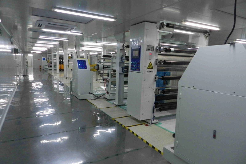
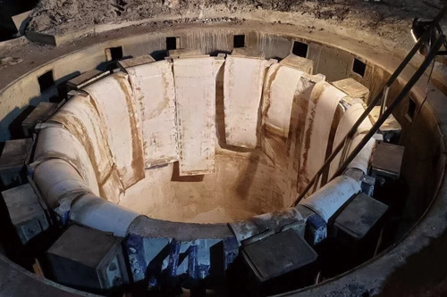
Customer-provided photograph of mica tape production equipment
Mica material and component illustration.

Muscovite Mica

Muscovite is a common starting point for rigid electrical insulation. Decide on the bonded grade together with the heat exposure and the way the finished part is supported.
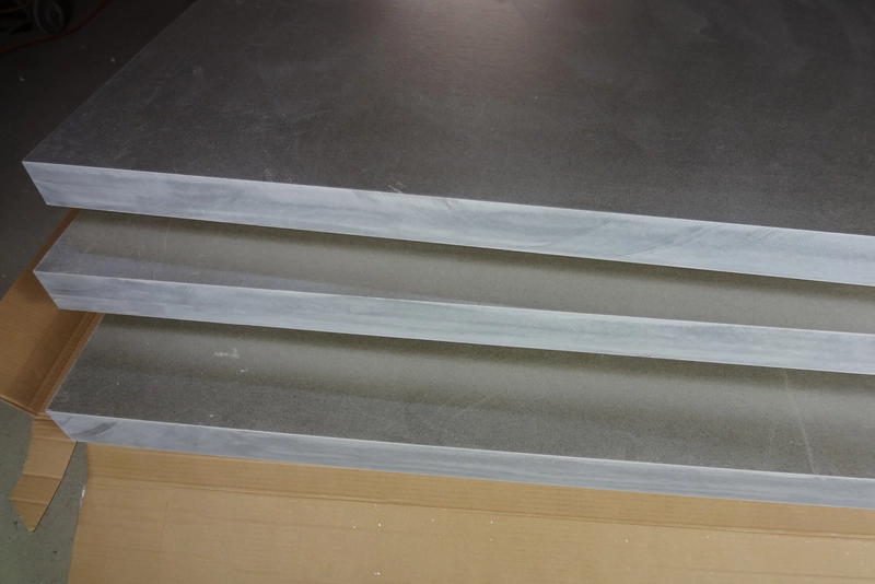
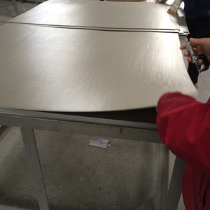
Mica sheet material example
Mica material and component illustration.

Phlogopite Mica

Phlogopite is often considered when heat exposure is a central selection factor. The finished laminate still needs to satisfy the electrical and mechanical demands of the assembly.

Designing Your Mica Component

Specify the finished profile, thickness, holes and critical fitting dimensions.

Match the machining method to the laminate and feature geometry.

Check finished-part dimensions, edge condition and assembly fit against the drawing.
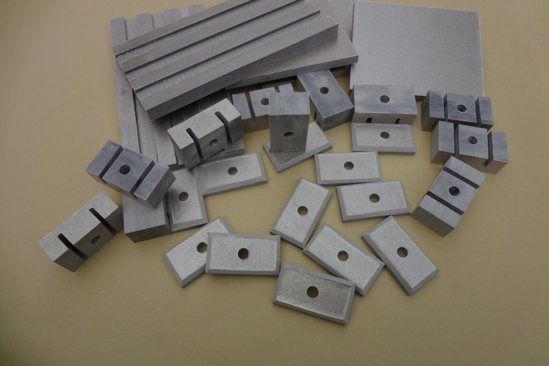
Customer-provided photograph of machined mica components
Mica material and component illustration.

A Clear Basis for Your Material Enquiry

Keep a product description, dimensional drawing and acceptance requirements together. This gives the material enquiry a clear basis and helps avoid selecting a laminate from a single isolated property.

Document

What it should establish

How it supports selection

Material description

Mineral, binder and rigid or flexible construction

Prevents substitution by appearance or mineral name alone.

Component drawing

Finished dimensions, holes, slots and locating faces

Separates blank requirements from finished component geometry.

Operating brief

Electrical, thermal and mechanical duty

Keeps material comparisons tied to equivalent service conditions.

Acceptance requirements

Checks that apply to the agreed product and finished component

Defines how the selected construction and finished part are reviewed.

Mica Material and Technical Documentation

Match the material construction to the way the finished component will be used.

Material & Fit

Match mica, binder and rigidity to the operating conditions.

Specify thickness, holes and supporting faces on the drawing.

Confirm material identity, test conditions and finished-part acceptance.

Main Benefits of Mica Sheets & Boards

  • Electrical and thermal insulation.
  • Rigid, flexible and thick formats for different components.
  • Drawing-defined profiles, holes and supporting faces.
  • Material and assembly requirements reviewed together.

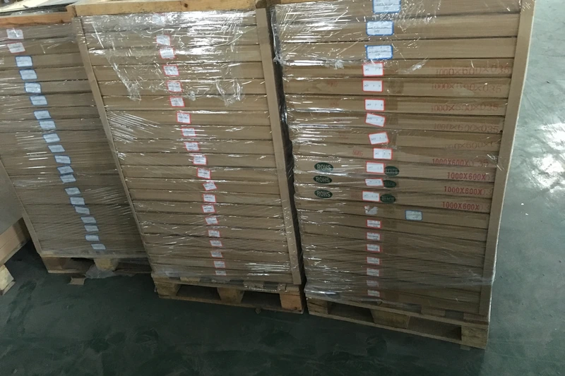
Mica material and machining examples; exact grade supplied to specification.

Mica Insulation Application Examples

Frequently Asked Questions

Start with the function of the insulation. Then select the mineral, binder and sheet construction together; a mineral name alone does not describe a finished laminate. For example, a flat carrier for a heating element needs a different balance of stiffness and fitting behaviour from a layer that wraps around a housing. Identify whether the part mainly separates conductors, interrupts a heat path or maintains a physical gap. Next consider how it is supported and whether it moves during installation or service. Once that role is clear, compare suitable constructions and define the dimensions. This sequence avoids choosing a mineral first and then forcing an unsuitable sheet format into the assembly. The final description should identify both the material and the job of the finished component.

Muscovite is commonly considered where electrical separation is central. Phlogopite is often considered for more demanding heat exposure. Compare the actual bonded grades before making a substitution. The comparison should include the bonded sheet rather than only the natural mineral. Two products can contain the same mineral but differ in binder, thickness or laminate structure. Those differences influence handling and performance in the installed part. If an existing design changes from one mineral to the other, review its electrical clearances, heat exposure and mechanical support instead of assuming a direct replacement. A useful comparison keeps the same test conditions and component geometry on both sides. That gives a clearer basis for selection than comparing the highest temperature or strongest electrical figure from unrelated catalogues.

No. A flexible sheet is a bonded insulation product. Mica paper can also be an intermediate material used to manufacture sheets, tapes or other constructions. The distinction matters when specifying what will arrive and how it will be used. A roll of intermediate paper is not automatically ready to replace a finished insulating layer in equipment. Likewise, a flexible bonded sheet may have a backing or reinforcement that changes its handling and face orientation. Describe the required construction, whether the material is supplied as a sheet or roll, and the shape it must take during installation. If it will be cut into a component, define the finished outline and any holes separately. Material form and finished component geometry should both appear in the enquiry.

A thicker blank can accommodate the depth needed for a machined component. The required finished geometry, support and loading still determine whether a particular construction is appropriate. Think about the part after machining, not just the starting stock. A spacer may need a substantial section at its contact faces while another component needs room for a recess or a deep opening. Removing material can leave thin walls or narrow bridges even when the original plate is thick. Those local features need consideration during cutting and installation. Identify the faces that carry load and the dimensions that establish the installed gap. A thicker blank is therefore a way to obtain the required geometry, not an automatic guarantee of strength or improved insulation in every assembly.

No. Separating commutator segments involves its own thickness, bonding and assembly requirements. A heater-board designation is not an adequate replacement specification. A commutator contains repeated insulating segments within a copper assembly. Local thickness differences can affect the accumulated fit, while compression and heat act on the bonded material during assembly and service. An ordinary heater sheet is generally selected around a different geometry and function. Even if the two products look similar, their construction and acceptance requirements may differ. A replacement review should use the actual segment outline, material description and assembly conditions. Keeping those requirements together is more reliable than selecting a plate solely because its mineral content or advertised heat resistance appears comparable.

Use the material description and agreed specification instead. Appearance can vary with the mineral, binder and surface finish. Colour can be helpful for recognising stock already controlled by a documented specification, but it is not a reliable independent test of composition. Lighting, surface texture and manufacturing differences can also affect what a photograph appears to show. When comparing materials, use the mineral and binder description, the rigid or flexible construction and the intended application. If a replacement component must match an existing design, refer to its drawing and material requirements. A sample can help assess handling and fit, but visual similarity by itself does not demonstrate electrical, thermal or mechanical equivalence.

Not automatically. Thickness does not establish formability; the binder and laminate construction affect how the material responds during fitting. A rigid laminate may become easier to deflect as its thickness decreases, yet this does not make it suitable for deliberate wrapping or repeated movement. The curve can introduce stress at the edges, around openings or between layers. A flexible product is chosen as a complete construction for the installation shape. Define whether the material will be bent once during fitting or will move during operation, and consider how it is held in position. Evaluate a representative piece in that arrangement. A flat sample that looks undamaged does not establish that a bent finished component will remain acceptable.

No. Exposure duration, electrical duty, mechanical support and the bonded construction matter. A brief heat exposure is not equivalent to continuous operation. The location of the component is important too. A machine setting or furnace temperature may not be the temperature reached by the insulation at its contact faces. Conversely, a local hot spot can be more severe than the surrounding environment suggests. Describe the expected exposure at the part, how long it lasts and whether heating is repeated. The binder and any reinforcement must be included in the assessment, because a bonded sheet is not simply raw mica. Select against the complete operating conditions rather than treating a single catalogue headline as permission for every use.

No. A material test and an assembled insulation system are different. Thickness, geometry, surface condition and the complete electrical design affect approval. The test normally describes a particular specimen under defined conditions. A real component adds holes, edges, fasteners and interfaces with other materials, and these features can change the available insulation path. Temperature and contamination may also differ from the test environment. Use the material result as one input to the electrical design rather than converting it directly into a working voltage by simple multiplication. The finished assembly should be assessed for its own geometry and duty. This distinction is especially important when changing thickness or substituting a different bonded construction in existing equipment.

No. A thicker part changes fit and heat flow as well as insulation distance. Select the complete construction for the intended function. Consider where the extra material would sit and what else it would change. It may alter the spacing of mating parts, the position of fasteners or the way a heat barrier contacts neighbouring components. It can also change stiffness without correcting a poorly supported area. For a curved installation, adding thickness may make fitting more difficult rather than more reliable. Define the function first and review thickness alongside construction, support and electrical geometry. A well chosen section is one that fits the complete design, not simply the largest dimension available for a particular material family.

A sheet is stock material. A finished part also has an outline, holes, edges and dimensional limits that need to match the assembly. This difference should remain clear in drawings and enquiries. A stock blank may deliberately include material that will be removed later, whereas a completed spacer or barrier must fit its intended location. Specify whether dimensions describe the starting blank or the finished article. For a finished part, identify critical fitting surfaces and the acceptable condition of cut edges. For stock material, define the useful area and any processing allowance needed for your own conversion. Keeping these two stages separate avoids an otherwise correct sheet being mistaken for a component that is already ready for installation.

Show the outline, units, holes and slots, along with critical dimensions and the current revision. Identify any faces that locate or contact another component. The most useful drawings distinguish functional requirements from general dimensions. A hole used to locate the part may need different attention from an opening that simply provides clearance. Show which surface acts as a reference and identify any narrow sections that must remain intact. If the part follows a curve or fits inside a stack, include enough assembly context to explain its final position. Avoid relying on an unscaled photograph for dimensional information. A clear drawing allows the material construction, cutting approach and finished inspection to be considered together without guessing which details are important.

No. Thickness, bonding and the detail being produced influence process choice. The finished edge and laminate condition are more useful acceptance criteria than naming a process alone. A simple outside profile in a thin laminate presents different challenges from a deep pocket or a narrow slot in a thick plate. Reinforcement can also change how the material cuts and how an edge should be inspected. The aim is to obtain the required outline while preserving the laminate around the feature. Review the first completed part for fit, cracking, chipping and separation where those conditions would affect use. Process choice should follow that geometry and acceptance requirement. It should not be assumed that a method used successfully on one mica product will suit every other construction.

An acceptable overall dimension does not rule out local damage. Check edges, holes and narrow sections for cracking or layer separation where they affect use. A damaged edge can occur close to a fastening hole, a narrow bridge or a surface that separates conductive parts. These locations may be more significant than a minor appearance variation on a nonfunctional face. Define which edges and features are important to the assembly, then inspect them after fabrication and handling. The inspection should consider the actual construction, because a reinforced flexible layer and a thick rigid laminate can show different forms of damage. Clear acceptance requirements help distinguish harmless cosmetic variation from a condition that could compromise fitting or the intended insulation function.

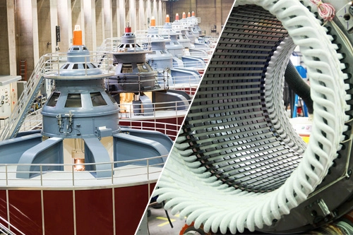
Mica-based insulation is used in heating assemblies. The chosen construction must suit the electrical separation, operating heat and way the element is supported. For a flat heating element, the mica part may act as a carrier as well as an electrical separator. In another arrangement it may form a fitted layer around a heated surface. Those roles call for different constructions and should not be grouped together simply under heater insulation. Consider where the element contacts the material, how the insulation is fixed and what happens during heating and cooling. Openings and narrow sections also need to fit the element layout. Review the finished component in the intended assembly rather than selecting a material only from a general list of heating applications.

Selected mica constructions are used in furnace-related insulation. Identify the location and duty; a liner, spacer and barrier do not necessarily require the same material. The part may be near the hot zone without experiencing exactly the same conditions as the furnace interior. Its actual exposure depends on position, neighbouring materials and contact with heated components. A flexible separating layer can be intended to accommodate movement within a lining, while a rigid component can have a supporting or spacing function. Specify that role before comparing materials. Include the intended joint layout, restraint or contact faces as appropriate. The complete furnace construction remains important, so a material described as suitable for furnace use should not be assumed to work at every location in every furnace.

No. Sealing involves compression, the joint and the medium being contained. A general electrical sheet should not be treated as a qualified gasket material. A gasket must work with the mating surfaces and the way the joint is clamped. It may need to conform during installation or retain an appropriate separation under load, depending on the design. A rigid electrical board can behave differently even if both products contain the same mica mineral. Identify whether the part is intended to seal, insulate or do both, and evaluate the complete construction for that role. Include the relevant exposure and joint conditions in the assessment. The presence of mica alone does not establish leak resistance, compression behaviour or compatibility with a particular sealing duty.

Ease of fitting does not establish resistance to repeated movement. Describe whether bending occurs only at installation or during operation. Installation flexibility and service movement are different requirements. A sheet that can be positioned around a curved housing may be held still once fitted. Repeated movement can instead stress a local bend, seam, opening or reinforced interface many times. Describe where movement occurs and how the layer is restrained, without assuming that the word flexible covers every type of motion. Assess a representative assembly under the movement and heating conditions it will actually experience. If the design requires a lasting folded shape or continual flexing, that requirement should be evaluated specifically rather than inferred from a simple hand bend.

Compare the same property, units, test direction and conditioning. Do not combine the strongest values from different constructions into a single product specification. Check that the materials being compared have equivalent constructions and that the figures describe the same type of result. A mineral property is not necessarily a laminate property, and a sheet specimen is not necessarily a finished component. Ambient measurements also should not be treated as interchangeable with measurements made while hot. Keep continuous exposure separate from a brief event and note whether dimensions or loads differ between the tests. Where these conditions are not available, treat the comparison as incomplete. Selecting the best number from each source can create a specification that no single real material has demonstrated.

Separate starting blank dimensions from the finished part dimensions. Include the features that control fit rather than relying on a sheet name alone. The specification should identify the faces and features that control installation. Overall length and width may be enough for a simple blank, but a machined spacer also needs its opening, contact faces and finished thickness defined. A shaped layer may require a developed flat outline as well as its installed arrangement. Identify the units and drawing revision so that the dimensions are read consistently. Where material will be removed during processing, show the relevant allowance separately. This makes it possible to assess the raw stock and the completed component without confusing the acceptance requirements for one with the other.

Review the old material function and the proposed construction, then assess the finished component under its intended conditions before approving the change. Begin by identifying why the original material was chosen. Electrical separation, thermal exposure, stiffness, compression and fitting behaviour can each be important, and a change that improves one may alter another. Compare the complete construction instead of matching colour or a generic product name. Then review whether the proposed replacement preserves the component geometry and the way it is supported or restrained. A representative finished part is useful for checking assembly fit and condition after the expected duty. Approval should be tied to that application, not to a claim that two broadly similar mica materials are universally interchangeable.

No. A named material family does not itself establish a test approval. Any required document must apply to the actual product and agreed supply. The document should identify what was tested or assessed and under which conditions. It matters whether the evidence concerns a mineral, a particular laminate, a component or a complete system. A statement on another product or supplier website does not establish that the material being purchased has the same approval. If a project requires a particular compliance document, make it part of the agreed product requirements and check that the supplied evidence applies to that construction. Keep material selection and certification review connected, but do not use a familiar family name as a substitute for product-specific documentation.

Compare the need for a flat support, a fitted layer, a thick machined blank or segment separation. This narrows the construction before detailed dimensions are agreed. Once the basic role is established, compare the installation conditions that distinguish the remaining options. A flat partition needs its mounting and clearances considered; a curved layer needs its fitting shape and restraint considered; a segment plate needs attention to the repeated assembly and thickness consistency. Note the heat exposure, electrical duty and important dimensions for that particular role. This creates a focused comparison rather than an open search across every mica product. The result should be a clear description of the component and its intended use, which can then guide discussion of the appropriate material construction.

Need a Supplier of Mica Sheets & Boards?

Contact Normanson Mica for standard material formats or drawing-based insulation components.