
Flexible Mica Sheets
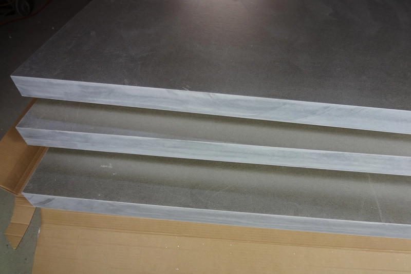
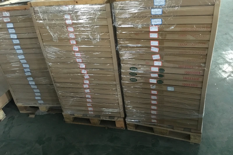
Mica-family material illustration; confirm the exact grade and finished form when enquiring.
Flexible mica sheets are considered when insulation must follow a surface rather than stand as a rigid board. A curved heater housing, a lining interface and a shaped electrical barrier each create a different installation problem, but all can require controlled conformity. The sheet combines mica with a binder system, sometimes with reinforcement, so it can be handled and shaped as a practical insulation layer.
• Material: Flexible Mica Sheets
• Format: discuss the required sheet or finished component
• Dimensions: review thickness, outline and fitting features
• Duty: thermal, electrical and mechanical requirements
• Machining: cut profiles, holes and openings by agreement
• Documentation: match the selected construction and application
Format and Dimensional Selection
|
Format |
Geometry to define |
Installation focus |
Useful drawing detail |
Design and verification note |
|---|---|---|---|---|
|
Flat sheet or pad |
Length, width and finished thickness |
Continuous coverage of the protected area |
Outline and any exposed electrical edges |
Distinguish the usable insulation area from clearance openings; a correctly sized outer rectangle alone does not describe coverage around a conductor or fastener. |
|
Wrap or strip |
Width, developed length and overlap |
Smooth contact around the component |
Installed diameter and seam position |
Include the actual installed profile, not only a diameter where the component is irregular, and keep the seam clear of features that would prevent seating. |
|
Cut gasket or separator |
Inner/outer profile and holes |
Fit without tearing at narrow sections |
Hole centres and minimum ligament widths |
Review the remaining material between an opening and the outer edge; this area must survive cutting, handling and the intended clamping arrangement. |
|
Reinforced laminate |
Total thickness and facing arrangement |
Handling strength and face orientation |
Identify which side faces the heat or conductor |
Record the facing position in the part definition so a sample and a production part are evaluated with the same surface against the adjoining component. |
|
Furnace slip-plane layer |
Circumference, height and joint layout |
Allow the intended lining movement |
Position of overlaps, joins and penetrations |
Use the lining arrangement to position joints and penetrations; a convenient stock width should not dictate a layout that obstructs the intended movement. |
Material Performance and Selection
|
Selection factor |
What it changes |
Practical evaluation |
Interpretation in the assembly |
|---|---|---|---|
|
Mineral type |
Balance between electrical insulation and higher-temperature exposure |
Compare the finished laminate, not the mineral alone |
A change in mineral type is not a complete specification change by itself; binder, reinforcement and the finished geometry must remain part of the comparison. |
|
Binder and reinforcement |
Bendability, handling and behaviour during heating |
Evaluate the full composite after its expected heat cycle |
Treat an added backing as a material change, including its orientation and thickness contribution, rather than as a handling accessory outside the insulation design. |
|
Conformability |
Ability to seat against the installation surface |
Inspect a representative bend for cracks or lifted layers |
Use the most demanding relevant curve and inspect after fitting; easy bending of a loose strip does not establish suitability for a sharp installed corner. |
|
Dielectric performance |
Electrical separation through the insulation |
Assess actual thickness, temperature and electrode arrangement |
Do not convert a general sheet description into an operating voltage; the complete insulation path and relevant service conditions determine the assessment. |
|
Compression response |
Fit within clamped joints or layered assemblies |
Check retained thickness under the intended load |
Check the laminate as installed, including overlaps and other layers, so local fit is not inferred solely from the nominal thickness of one sheet. |
|
Surface and cut edges |
Installation integrity at seams and fasteners |
Reject tears, loose layers or damaged narrow features |
Focus inspection on the features that experience installation stress, particularly cut-outs, corners and seams, rather than accepting a part only because its broad surfaces look clean. |
Flexible mica sheets are considered when insulation must follow a surface rather than stand as a rigid board. A curved heater housing, a lining interface and a shaped electrical barrier each create a different installation problem, but all can require controlled conformity. The sheet combines mica with a binder system, sometimes with reinforcement, so it can be handled and shaped as a practical insulation layer. This does not mean it behaves like a soft rubber or can be folded into any corner. The useful question is whether the selected construction follows the intended geometry without damage and stays correctly positioned after assembly. A broad curve, a narrow opening and a clamped flat pad should therefore be treated as distinct design conditions. Choosing flexible material begins with the installed shape, not merely with how easily a loose sample bends. The retention method should keep that fitted layer in the position the insulation design requires.
The mineral and the rest of the laminate must be considered together. Muscovite and phlogopite offer different starting points for thermal and electrical selection, while the binder and any backing influence handling, surface contact and behaviour during heating. A reinforced electrical composite is not automatically interchangeable with a furnace separating sheet, even if both are described as flexible mica. Similarly, nominal thickness does not reveal which layers make up that thickness or which face should contact an adjacent component. Identify the complete construction before comparing alternatives. Separate continuous heat exposure from short excursions, and distinguish the electrical function from the mechanical need to fit a curve. This approach keeps a convenient handling characteristic from becoming an unsupported claim about temperature, voltage or durability in a different application.
For practical selection, connect the material description to a finished-part drawing and a representative installation. Define coverage, cut-outs, seams and overlaps, together with the way the layer will be retained. Where one face differs from the other, keep its orientation clear. Evaluate the sample after cutting and after it has experienced the relevant bend, contact pressure and heating cycle; a flat sheet alone cannot demonstrate those conditions. The information below organises flexible mica around these decisions, from format and dimensions to construction, fabrication and application. It helps distinguish a wrap from a separator or gasket without assuming that every use requires the same laminate. A useful specification describes both the material and its job in the assembly, making comparisons more meaningful than a choice based solely on appearance or a headline rating.
Designing Your Mica Component
Flexible mica parts begin with a flat layout that accounts for the installed shape. Define the outline, cut-outs and narrow sections, then add seam and overlap information for wraps. An asymmetric laminate also needs a clear facing direction so the cutting layout remains connected to assembly.
Cutting or die tooling should suit the thickness, reinforcement and quantity. Inspect a representative first cut rather than assuming that a method used for an unbacked sheet will leave the same edge on a reinforced composite. Look for torn corners, lifted layers and reinforcement pulled away from the mica.
Check the fabricated part on the intended surface. A profile that measures correctly while flat may still be difficult to install around a tight curve or opening. Review the condition after the relevant bending, retention and heating sequence, keeping the sample construction consistent with the material intended for the finished assembly.
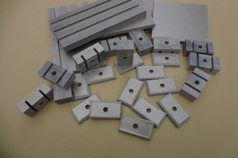
Match the material construction to the way the finished component will be used.
Main Benefits of Flexible Mica Sheets
Where This Construction Fits

Curved heater insulation
A conformable layer can follow a cylindrical or irregular surface. Electrical clearance, retention and the condition after heating remain part of the heater design.

Furnace lining interfaces
Flexible mica can serve as a separating or slip-plane layer within a lining system. Joints and overlaps should preserve the movement allowed by the furnace construction.
Layer and barrier insulation
Selected flexible composites can separate coils or adjacent components. The complete laminate must suit the electrical system rather than being chosen only for easy bending.
Shaped gasket and joint separators
Cut flexible mica can provide a shaped separating layer at a joint. The material and profile must suit the mating surfaces and clamping conditions; a thermal separator should not be treated as a qualified fluid seal simply because it has a gasket outline.
Handling and Assembly Review
Keep the material supported during handling and inspect the finished edges, openings and contact faces before assembly. Review fastening, electrical clearances and heat exposure against the selected construction. A material-level property is not a rating for the complete equipment.
When is flexible mica preferable to rigid mica?
Flexible mica is preferable when the insulation must follow a curved housing, wrap around a component or fit a shaped interface without behaving like a self-supporting board. Its usefulness comes from conformability, not from an assumption that flexible material is always thinner or more heat resistant. A rigid sheet remains the more appropriate starting point when the part must retain a flat shape or support other components. Compare the installed geometry as well as the material label: a broad curve, a narrow corner and a clamped flat pad impose different demands. Check whether the chosen construction sits against the surface without cracked edges, lifted layers or excessive spring-back. Where both stiffness and conformity are needed, assess the complete assembly rather than forcing either material into the wrong role. For example, a wrap retained against a housing and a flat spacer held between components solve different installation problems. Comparing those roles first helps prevent an easy-to-bend sample from being selected for a part that actually needs dimensional rigidity.
Is every flexible mica sheet the same material?
No. Flexible mica describes a family of constructions rather than one interchangeable material. The mica mineral, binder, reinforcement and total thickness can differ even when samples look similar. One construction may serve as a thermal separating layer, while another is a reinforced electrical insulation composite. Identify the complete laminate and the function of any facing material before comparing alternatives. Then assess behaviour under the proposed heat, clamping and installation conditions. Hand bending can help assess handling, but it does not establish electrical suitability or performance after heat exposure. Similar flexibility is therefore not proof of equivalence.
Does flexible mean it can be folded sharply?
No. A sheet that follows a smooth curve is not necessarily suitable for a sharp crease. Folding concentrates deformation into a narrow line, whereas bending spreads it over a larger area. The mica layers, binder and any reinforcement may respond differently at that line, so an apparently intact outer face is not enough to judge the result. Use a representative piece to reproduce the proposed installation radius and inspect both faces and the edges for cracking or separation. Also check the condition after the relevant heating and clamping cycle. If the design requires a corner, consider how the part can be supported and retained without forcing the sheet into an unverified fold. Flexibility should be evaluated at the actual thickness and geometry, not inferred from a thinner sample.
How should sheet thickness be selected?
Select thickness by considering the insulation function and the available space together. A thicker flexible sheet changes the electrical path, heat flow, installed curvature and compression within a joint; it does not simply provide more of every benefit. Begin with the required coverage and the space left after adjacent components are assembled. Then consider the smallest curve, the way the sheet is retained and whether it will be compressed. For a layered or reinforced product, total thickness also includes materials other than mica. A useful comparison therefore uses the actual laminate construction and installation conditions. Confirm that the chosen thickness can seat properly without damaged edges or gaps, and assess the complete assembly rather than relying only on a nominal sheet measurement. If the design changes from a flat pad to a wrap, revisit thickness rather than carrying the old selection forward unchanged. The same material must now satisfy a curvature requirement as well as the original insulation duty.
Can it be cut into gaskets?
Flexible mica can be cut into gasket and separator shapes, but a cut outline alone does not establish sealing performance. The joint must also suit the material’s construction, compression response, mating surfaces and service conditions. A sheet selected as a thermal separator may not be an equivalent substitute for a gasket whose main duty is fluid sealing. In the drawing, distinguish the outer profile, openings, fastening holes and narrow sections that remain between them. These features affect handling and the risk of damage during cutting or installation. Inspect a representative cut part for tears, lifted layers and reinforcement pulled from the edge. Assess how it seats in the actual joint under the intended clamping conditions before treating the geometry and material as an established combination.
Why consider a reinforced version?
Reinforcement can improve handling or resistance to tearing, especially around holes and narrow cut features. It is not automatically necessary or beneficial for every design. A facing changes total thickness, bendability, surface contact and behaviour during heating, so it must be considered as part of the laminate. Identify its material and position before comparing samples. For a one-sided construction, record the required orientation. Check the benefit on a representative cut and installed part. Better handling does not by itself establish a higher service temperature or improved electrical insulation; those are separate requirements for the complete construction.
Which side should face the hot surface?
The hot-side orientation depends on the complete laminate, particularly when the two faces are different. There is no reliable universal rule that the mica face or the reinforced face must always point toward the heat. Identify the materials on each face and consider what each will contact: a heated metal surface, another insulation layer or an exposed environment. The temperature at an interface may also differ from the surrounding air temperature. Record the intended orientation on the installation drawing so that it remains consistent during assembly. A representative sample should use the same facing arrangement, contact pressure and heat exposure as the finished part. Do not reverse an asymmetric laminate simply because the alternative orientation appears easier to install.
Can one temperature rating describe every application?
No. A single headline temperature cannot fully describe how a flexible mica laminate performs in different applications. Continuous exposure and a short excursion are different conditions, and the binder and reinforcement may behave differently from the mica mineral itself. The atmosphere, contact with other materials and mechanical restraint also belong to the evaluation. When comparing materials, establish whether the quoted temperature concerns a mineral, a finished sheet or a complete insulation system. Then distinguish the hot-side exposure from the temperature that other parts of the assembly experience. For a flexible installation, also consider the condition after heating: a sheet that fitted well initially may not retain the same handling behaviour. Use the relevant construction and duty cycle as the comparison basis, not the largest temperature printed in a general description. A reinforced electrical composite and a furnace separating sheet may both contain mica while using quite different supporting materials. Their descriptions should not be merged into a single universal rating simply because the mineral family is shared.
What is a furnace slip-plane application?
A furnace slip-plane application uses a separating layer within the lining construction to accommodate relative movement as components expand and contract. Flexible mica is considered for this role because it can follow the installation geometry while providing a mica-based barrier. It is not simply an extra sheet placed anywhere behind the lining. The position, coverage, joints and overlaps must fit the furnace design and preserve the intended movement. Pay particular attention to penetrations and areas where the layer could become trapped or damaged during installation. The selected laminate must also suit the temperature and materials at that interface. Evaluate it as part of the lining system rather than assuming that a material suitable for one furnace arrangement will work unchanged in another.
Can flexible mica replace motor insulation directly?
No direct replacement should be assumed. Motor insulation includes different functions, such as separating layers, lining slots and insulating conductors; a flexible mica product suitable for one of these roles may not suit another. A thermal wrap is especially different from a reinforced composite intended for a defined electrical insulation system. Compare the complete construction, including binder and backing, with the function of the original material. Thickness, installed geometry, processing and heat exposure also affect the comparison. A sample that bends into position only demonstrates part of the installation requirement. Electrical and thermal suitability must be assessed within the relevant assembly, and a change of material should not be accepted solely because both products are described as flexible mica.
How are strips and wraps dimensioned?
Dimension a wrap in both its flat and installed states. Define width and developed length, then identify the installed diameter or profile, seam position and overlap. This distinguishes coverage from material used at the joint. Include cut-outs and fastening features that affect fit, plus face orientation for an asymmetric laminate. Check a representative wrap on the actual geometry: it should seat smoothly without forcing edges or holes, and the seam should remain where intended. The final drawing should describe a repeatable installation rather than merely a rectangle cut from a larger sheet of material.
What should be inspected after cutting?
Inspect the outline, holes and cut edges for damage that could affect installation. On an unbacked sheet, look for tears, cracked corners or lifted mica layers; on a reinforced laminate, also check for pulled fibres or separation between the facing and the mica. Narrow sections between holes and the outer edge deserve particular attention because they can be damaged during handling even when the broad faces look sound. Confirm that the cut profile matches the intended part and can be installed without forcing it into place. If the sheet will be bent after cutting, inspect the shaped sample as well as the flat one. A neat-looking outline is helpful, but it should not hide damage at the locations that carry the installation stress.
Does adding more layers solve every insulation problem?
No. Adding layers changes more than total thickness. It creates additional interfaces, alters the available fit and may change compression or the way the insulation follows a curve. A stack that looks satisfactory on a flat bench may move, bunch or leave gaps when installed around a shaped component. Consider how each layer is retained and how joints or overlaps are arranged. For electrical insulation, evaluate the complete path through and around the stack rather than assuming that separate sheet ratings can simply be added. For a thermal barrier, the interfaces and mounting conditions also matter. Additional layers can be part of a suitable design, but they should be assessed as a new construction under the intended assembly and service conditions.
What makes an installation sample useful?
An installation sample is useful when it reproduces the features that make the real application difficult. Use the intended laminate and thickness, then include the relevant curve, seam, cut-outs and retention method. A small flat sample can show surface condition, but it cannot demonstrate how a wrap fits or how a narrow section survives installation. Inspect the sample before fitting, after fitting and after the relevant heating or clamping cycle. Compare the same locations so that cracking, lifted layers or changes in seating are easier to identify. Keep the orientation and assembly method consistent with the proposed drawing. This turns the sample into a practical check of material and geometry together, rather than a general demonstration that the sheet can bend. Where several features are present, include the difficult ones instead of selecting only a broad, easy curve. A sample with the actual seam and smallest relevant cut-out is more informative than a larger but simplified piece.
What distinguishes a roll from a finished insulation part?
A roll describes how material is supplied and handled before it becomes an installed component. A finished insulation part also has a defined outline, thickness, face orientation, seam arrangement and relationship to the surrounding assembly. Those details can affect performance even when the raw material is unchanged. For example, a strip intended to wrap around a component needs an installed diameter and overlap, while a flat separator needs its openings and supported edges defined. Cutting and forming introduce additional inspection points, including tears, edge separation and damaged reinforcement. Treat the roll as feedstock with a particular construction, then define the finished part around its actual function. Supply format alone does not establish that the resulting component is ready for a specific electrical or thermal application.
Let Us Talk Now
Share your material, dimensions, quantity and application. We will review the details with you.