
Thick Mica Plates
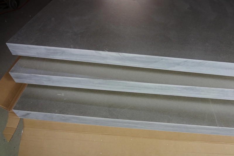
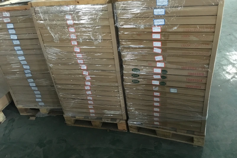
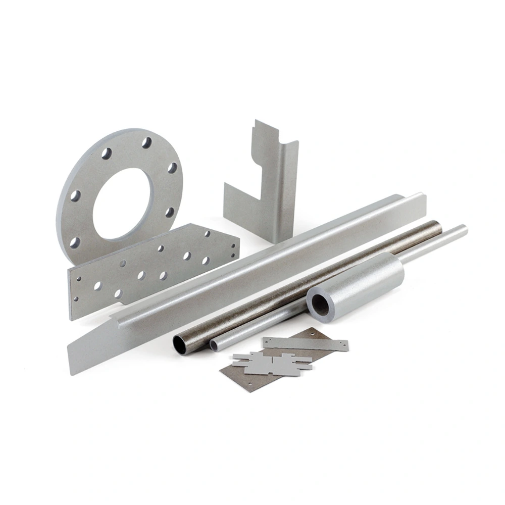
Mica-family material illustration; confirm the exact grade and finished form when enquiring.
Thick mica plate provides a rigid starting section for insulation components that cannot be made adequately from a loose thin sheet. The material is commonly a bonded laminate, bringing together mica and a binder in a board that can be cut or machined into a useful shape. Its role may be to establish separation, form a thermal barrier or provide the geometry of an insulating spacer.
• Material: Thick Mica Plates
• Format: discuss the required sheet or finished component
• Dimensions: review thickness, outline and fitting features
• Duty: thermal, electrical and mechanical requirements
• Machining: cut profiles, holes and openings by agreement
• Documentation: match the selected construction and application
Format and Dimensional Selection
|
Part feature |
Dimension to define |
Why it matters |
Inspection focus |
Design and verification note |
|---|---|---|---|---|
|
Plate blank |
Length, width and nominal thickness |
Provides material for the finished profile |
Flatness, edge condition and machining allowance |
Treat extra stock for machining as an allowance, not as a finished feature; the usable part must still meet its own outline and contact requirements. |
|
Finished section |
Thickness at functional contact areas |
Controls installed gap and support |
Measurement positions and local variation |
Identify the surfaces that actually mate with neighbouring parts so thickness measurements describe the installed gap rather than an unrelated area of the blank. |
|
Holes and slots |
Size, location and orientation |
Positions the insulation around fasteners or conductors |
Distance to edges and adjacent features |
Assess what remains between openings and edges; changing a hole position can change the component even when its outer dimensions are unchanged. |
|
Profiles and recesses |
Contour, depth and remaining wall |
Determines fit and local stiffness |
Corners, thin webs and exposed layers |
Reference recess depth to the intended finished face and review the remaining wall, avoiding a drawing that defines each cut without describing the resulting section. |
|
Assembly interfaces |
Contact faces and support span |
Defines where the plate carries load |
Seating, clearance and concentrated pressure |
Check the part on the actual support arrangement; forcing a plate to seat can conceal interference and introduce a load condition that the drawing did not intend. |
Material Performance and Selection
|
Design factor |
Material consideration |
Evaluation in the component |
Interpretation in the assembly |
|---|---|---|---|
|
Electrical isolation |
Mica is used as an insulating phase |
Check the full path, cut edges and mounting arrangement |
Include the route around edges and mounting features in the review rather than assessing only the path through the broad, full-thickness portion of the plate. |
|
Heat exposure |
Mineral and binder form one thermal system |
Separate continuous exposure from short excursions |
A bonded plate is not rated by the mineral alone; retain the actual construction and exposure duration when interpreting thermal information. |
|
Section stiffness |
Thickness and geometry work together |
Assess the support span rather than thickness alone |
Revisit stiffness after holes or recesses are added, because the remaining geometry may differ substantially from the original unmachined section. |
|
Compressive loading |
Load distribution affects local stress |
Avoid unsupported or point-loaded contact areas |
Identify small contacts and uneven seating before assuming that a thicker blank resolves loading; the local arrangement remains part of the assessment. |
|
Machined integrity |
Laminated material can chip or separate |
Inspect hole exits, corners and thin walls |
Inspect both the visible face and accessible exit edges after machining, as a clean entry can coexist with damage elsewhere around the feature. |
|
Environmental exposure |
The binder and interfaces also contact the environment |
Review actual fluids, moisture and thermal cycling |
Evaluate the environment experienced by the assembled part, including its interfaces, rather than applying a broad chemical-resistance description without reference to the actual exposure. |
Thick mica plate provides a rigid starting section for insulation components that cannot be made adequately from a loose thin sheet. The material is commonly a bonded laminate, bringing together mica and a binder in a board that can be cut or machined into a useful shape. Its role may be to establish separation, form a thermal barrier or provide the geometry of an insulating spacer. The word thick does not identify one universal grade or guarantee a particular load capacity. A broad blank, a recessed part and a component with closely spaced holes can behave differently even when their original stock thickness is identical. Selection therefore begins with the finished section and the way it will be supported, rather than treating a larger amount of material as an automatic solution.
Muscovite and phlogopite are different mineral starting points, but the complete laminate is the material that goes into the assembly. Binder, lamination and geometry influence how a plate is machined and used. Compare thermal exposure separately from electrical separation, then consider where the component contacts other parts or carries an assembly load. A room-temperature electrical result does not describe every heated installation, and the heat resistance of the mineral is not a complete rating for the bonded board. Similar caution applies to machining: an outline may be straightforward while a narrow remaining wall requires closer review. Considering these factors together helps distinguish the material’s general insulating role from the specific conditions that a finished component must meet. Neither colour nor overall thickness provides that complete description.
A useful drawing separates the stock blank from the functional part. Identify finished thickness at contact areas, hole locations, recess depths and the faces that establish fit. Allowance for machining belongs to the blank definition rather than to an installed clearance. Inspect the resulting component at hole exits, corners and exposed layers, not only on its broad surfaces. Trial fitting should show that it seats without force and retains the intended separation around mounting hardware. The information below connects these practical decisions with material selection and inspection, helping organise a plate requirement around its job in the equipment. It also makes changes easier to evaluate: moving a hole or replacing a loose stack with a bonded section can be reviewed as a design change rather than accepted because the material name remains familiar. The resulting definition should make the important mating relationships visible without requiring an inspector to infer them from stock dimensions.
Designing Your Mica Component
Define the finished component before choosing a cutting method. Separate blank dimensions from functional faces, hole positions and recess depths. Mark the features that control fit so machining allowance is not confused with the thickness or clearance needed in the installed assembly.
Sawing, drilling, milling or another suitable process should account for the laminate, section depth and outline. Support the workpiece and review a representative first component at hole exits, corners and thin walls. A process established for a thin punched sheet should not automatically be transferred to a deep plate.
Complete the review with dimensional inspection and trial fitting. Check that the part seats without forcing and that machined edges remain intact around conductors or fasteners. Where heat or mechanical loading is relevant, assess those conditions with the finished geometry rather than drawing conclusions solely from an unmachined stock sample.
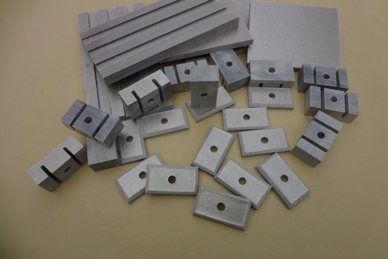
Match the material construction to the way the finished component will be used.
Main Benefits of Thick Mica Plates
Where This Construction Fits

Thermal separation plates
A rigid barrier can limit direct thermal contact within an equipment assembly. Thickness, exposed area and mounting details all affect the installed thermal path.

Electrical spacers and supports
Machined plate can establish a separation between conductive parts. The design must also retain clearance around fasteners, edges and openings.
Custom insulation components
Profiles, holes and recesses can adapt a plate to a particular assembly. Geometry should preserve enough material around load-bearing and mounting features.
Heater terminal insulation
A machined mica plate can form a rigid insulating detail around heater connections. The component must retain the intended separation around terminals and mounting hardware while fitting the local heat exposure and support arrangement.
Handling and Assembly Review
Keep the material supported during handling and inspect the finished edges, openings and contact faces before assembly. Review fastening, electrical clearances and heat exposure against the selected construction. A material-level property is not a rating for the complete equipment.
What makes a mica plate a thick plate?
Thick plate describes a relatively deep, rigid mica laminate used when thin sheet cannot provide the required section. It is not one universal grade or a single thickness boundary. The practical distinction is its role as stock for machined spacers, barriers or shaped insulation components. Compare actual thickness and construction rather than relying on the category name. Also consider holes, recesses and the support span: a substantial blank can still contain a vulnerable narrow wall after machining. Overall thickness is therefore a starting point for selection, not a complete description of the finished part’s suitability.
Is thick mica the same as a solid mineral block?
No. Industrial thick mica plate is commonly a bonded laminate, whereas natural mica block is a different material form. A laminate brings together mica with a binder to create a larger rigid section; its behaviour therefore depends on the complete construction, not just the mineral. This distinction matters when comparing machining, heat exposure and electrical properties. A value or handling method described for natural mica should not automatically be applied to a bonded board. Identify whether the proposed material is a plate laminate or a natural block before comparing dimensions and performance. For a machined component, also examine the finished edges and features, where the layered construction can become more important than the appearance of the broad faces. When reviewing samples, note which surfaces are original stock faces and which have been machined. This keeps differences in surface appearance from being mistaken for a difference in mineral type or for evidence that a plate is a natural block.
Does a thicker plate always insulate better?
Not always. Increasing thickness can change the electrical path and the heat transferred through a plate, but the installed result also depends on the material, temperature, contact area and mounting arrangement. Heat may pass through fasteners or adjacent components, and electrical separation can be limited by paths around an edge rather than through the full plate thickness. A thicker section also occupies more space and changes the mechanical geometry. Start with the function of the barrier and identify the relevant heat or electrical path. Then evaluate the selected thickness within that assembly. Treating thickness as the only performance measure can overlook mounting details or exposed edges that remain unchanged when a larger blank is selected.
Can it be drilled or milled?
Rigid mica plate can be drilled or milled with an appropriate process, but it should be treated as a layered material rather than as a uniform metal block. Tool choice, support and cutting conditions influence whether holes and profiles are produced cleanly or leave chips and separated layers. The part geometry matters too: a deep hole, a thin wall and a broad straight edge impose different demands. Define which dimensions are functional and what edge condition is acceptable before machining. Inspect the first component particularly at hole exits, internal corners and narrow sections. The fact that a process can remove material does not by itself establish a finished tolerance or an undamaged part. Those outcomes must be evaluated on the actual construction and geometry.
Why are hole positions important?
Hole positions determine how much material remains around a fastener or between adjacent features. A hole placed close to an edge leaves a narrow ligament that may be harder to machine and more vulnerable during assembly. Position also affects whether the part fits without forcing, whether a fastener bears where intended and whether the insulation maintains the required separation around conductive components. Define the hole relative to functional reference features, not only to convenient edges on a rough blank. Review the remaining wall and the way the component is supported or clamped. When checking a first part, inspect both the hole geometry and the surrounding layers. A correctly sized hole can still be unsuitable if its location leaves a damaged or poorly supported section. This review is especially valuable when modifying an existing drawing. Moving a mounting hole to match another component can change the remaining section, even if the plate outline and thickness are unchanged. Recheck the local geometry rather than approving the revision solely because the new hole still lies inside the outline.
Should every hole have the same tolerance?
No. Tolerances should reflect what each hole does in the assembly. A locating hole may control alignment, while a clearance opening mainly needs to avoid interference; applying the same requirement to both can obscure what is actually critical. Describe the size and position in relation to the mating parts and distinguish these requirements from the general blank dimensions. Also consider the condition of the material around the hole, especially at exits and near edges. A narrow numerical tolerance is not useful if the surrounding laminate is damaged. The first-part review should therefore check fit, location and edge integrity together. Use the drawing to communicate functional priorities rather than assigning uniformly tight limits without an assembly reason.
Can thick plate replace several loose sheets?
A thick plate may replace loose sheets in some rigid insulation designs, but equal total thickness does not establish equivalence. The constructions have different interfaces and mechanical behaviour: loose layers may move relative to one another, while a bonded plate forms a consolidated section. Substitution can also change fit, contact and load distribution around fasteners. Review the original purpose of the layered arrangement before changing it. Compare finished dimensions, mounting, electrical separation and thermal exposure in the complete assembly. Simplifying handling can be useful, but convenience alone is not evidence that the replacement performs identically.
How do muscovite and phlogopite differ in selection?
Muscovite and phlogopite provide different mineral starting points for a mica laminate. Phlogopite is commonly considered where higher-temperature exposure is a central requirement, while muscovite is widely used in electrical insulation applications. These broad tendencies do not replace comparison of the finished product. Binder, thickness and construction influence the plate, and the electrical result depends on the relevant test and service conditions. Begin with the component’s primary demands, then assess the complete laminate against them. Avoid selecting by colour alone or treating a mineral temperature as a guaranteed operating limit for a bonded board. For a thick machined part, include geometry and edge integrity in the comparison rather than making the mineral choice separately from the design.
Why separate blank and finished dimensions?
Blank dimensions describe the starting stock; finished dimensions describe the component that must fit and function in the assembly. Keeping them separate allows for material that will be removed during cutting or machining without confusing it with the required installed size. A blank may need extra material around an outline or on a face, but that allowance is not part of the finished clearance or contact thickness. Identify which faces and features establish the final geometry, including holes, recesses and mounting surfaces. Inspect the finished part against those references rather than assuming that a correctly sized blank guarantees a correct component. This distinction is particularly useful when only selected areas of a thick plate are machined or when functional faces require closer attention than the outer stock edges. Where the outline contains a recess, identify whether its depth is referenced to an original face or a finished one. Otherwise, two individually plausible measurements can describe different remaining wall thicknesses in the installed part.
What should be checked on machined edges?
Check machined edges for chips, cracks and lifted or separated layers, especially where the cutting process enters or exits a hole, turns a corner or leaves a narrow wall. The inspection should relate the damage to the part’s function rather than focus only on appearance. An irregular edge beside a conductor, for example, may deserve different attention from a nonfunctional stock edge that will be removed later. Confirm that the contour is correct and that the surrounding laminate remains intact. Inspect both sides where access allows, because a clean entry face can conceal damage at the exit. Define acceptance around the actual finished feature, and do not treat a smooth broad surface as evidence that every machined edge is sound.
Can a plate carry concentrated loads?
Whether a plate can carry a concentrated load depends on the laminate and the component geometry; it cannot be determined from the word thick alone. A small contact area introduces local stress, and a plate spanning an unsupported gap behaves differently from one resting on a broad, even surface. Holes, recesses and thin remaining walls can further change the way load is carried. Identify the contact areas and the support arrangement before evaluating the material. Avoid assuming that a larger overall thickness compensates for every point load or assembly mismatch. The first-part or assembly review should check seating and load distribution as well as dimensions. A mica insulation part should not be treated as a structural member without evaluating that specific duty.
Is the room-temperature electrical value enough?
No. A room-temperature electrical value describes performance under particular test conditions, not every condition inside an operating assembly. Temperature, material thickness and the geometry of the insulation path matter, and the binder and interfaces form part of the finished laminate. The installed component also includes cut edges, mounting holes and nearby conductors that may not be represented by a simple flat test specimen. Use electrical information that corresponds to the selected construction and relevant conditions, then consider the complete path through and around the component. This does not mean room-temperature data are useless; they are one part of the comparison. They should not be converted directly into a universal operating voltage or used to overlook the effect of heat and assembly details.
What information distinguishes a thermal barrier?
A thermal barrier is defined by the heat path it must interrupt. Identify the hot-side exposure, protected area, available thickness and mounting arrangement. Contacts, fasteners and adjacent components may introduce additional paths, so the installed result is not determined by material alone. Distinguish continuous exposure from short excursions and consider whether the plate also carries a mechanical load. Assess the complete laminate rather than using the mineral’s heat resistance as a product rating. These details allow a meaningful comparison of designs; a mica name and a temperature figure cannot describe the whole assembly’s thermal behaviour.
How should a machined part be protected?
Support a machined mica part and protect its edges, holes and faces from impact, contamination and moisture before installation. A thick component may look robust while still containing delicate narrow sections or exposed layers at a machined feature. Avoid handling that places the load on those areas, and keep the part from being forced against other components during storage or transport. Before assembly, check that the functional surfaces are clean and that no chips or lifted layers have appeared since machining. Protection should follow the finished geometry rather than only the outside size of the original blank. A broad flat plate and a deeply profiled component may need different support even when they were cut from the same material.
What should a first-part review include?
A first-part review should connect the drawing, the material and the assembly. Check the functional dimensions, hole positions and profile, then inspect edges, corners and thin sections for damage from machining. Trial fit the component without forcing it into position so that seating or clearance problems are visible. Where the part is exposed to heat or load, assess the relevant conditions rather than judging only the uninstalled component. The review should distinguish a stock-size issue from a finished-feature issue and identify which faces actually contact other parts. Record the accepted construction and geometry together. This creates a useful basis for subsequent parts and avoids approving a material sample while leaving the critical machined features or mounting arrangement unexamined. If a trial fit reveals interference, identify its location before altering the part. Removing material from an unexamined edge may solve the immediate fit problem while changing a functional clearance or leaving a thinner section than the drawing intended.
Let Us Talk Now
Share your material, dimensions, quantity and application. We will review the details with you.