
Epoxy-Bonded Commutator Mica Plates
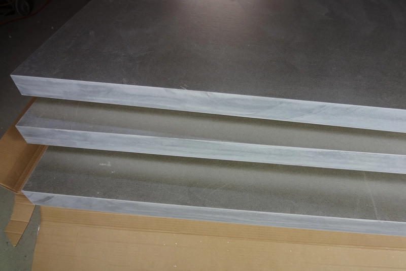
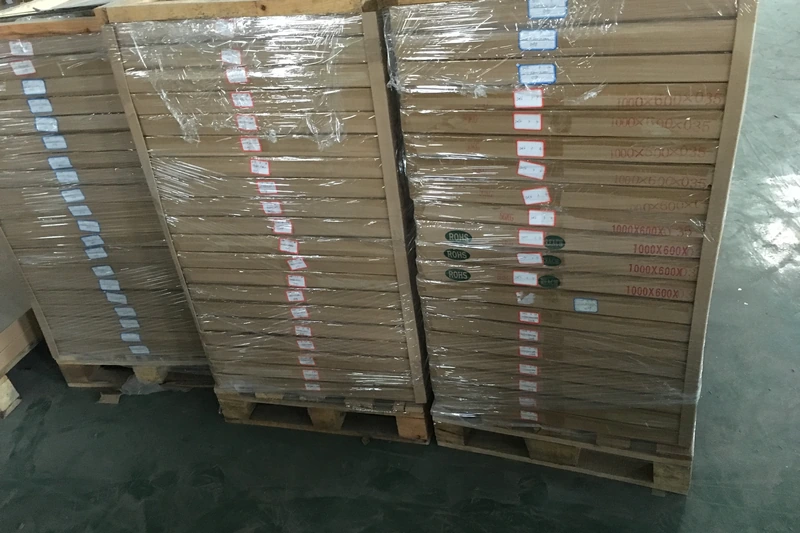
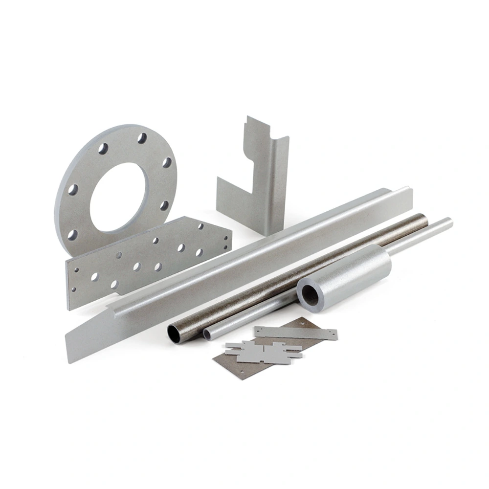
Mica-family material illustration; confirm the exact grade and finished form when enquiring.
Commutator mica plates provide the insulating separation between neighbouring copper segments in a commutator assembly. Copper carries the current, while the segment insulation must fit a repeated stack that also experiences clamping, heat and rotation. The material is therefore selected for more than a general ability to resist temperature.
• Material: Epoxy-Bonded Commutator Mica Plates
• Format: discuss the required sheet or finished component
• Dimensions: review thickness, outline and fitting features
• Duty: thermal, electrical and mechanical requirements
• Machining: cut profiles, holes and openings by agreement
• Documentation: match the selected construction and application
Format and Dimensional Selection
|
Requirement |
Definition for the segment |
Assembly relevance |
Inspection focus |
Design and verification note |
|---|---|---|---|---|
|
Insulation thickness |
Finished thickness and permitted variation |
Sets separation within the copper stack |
Measure at defined positions across the segment |
Keep the measuring locations related to the contact area; one stock-sheet reading cannot describe the thickness distribution of all finished pieces in the stack. |
|
Segment outline |
Width, length and functional contour |
Matches the adjacent copper bars |
Profile fit and edge condition |
Reference the contour to functional copper features and inspect the mating relationship, not merely the outside rectangle from which the segment was cut. |
|
Plate preparation |
Blank size and finishing allowance |
Determines how finished segments are produced |
Surface condition and uniformity |
Identify whether stock preparation includes a separate thickness-finishing step so profile accuracy is not mistaken for completion of every dimensional requirement. |
|
Compressed stack |
Loading condition and dimensional response |
Affects the assembled commutator geometry |
Retained separation after the specified cycle |
Compare the loaded arrangement with the intended process, rather than using the loose nominal thickness as the only description of assembled separation. |
|
Finishing interface |
Relationship to the copper working surface |
Links insulation to final assembly operations |
Follow the commutator drawing and process |
Keep material preparation and final assembly finishing distinct; the segment must be evaluated in relation to the equipment-specific commutator process. |
Material Performance and Selection
|
Selection factor |
Why it is relevant |
Acceptance approach |
Interpretation in the assembly |
|---|---|---|---|
|
Mica construction |
Paper and splitting laminates are not identical |
Identify the actual construction before comparing grades |
A change between paper-based and splitting-based stock remains a construction change even when dimensions match; compare the finished segment and its intended function. |
|
Binder and cure |
Influence cohesion and response to heating |
Assess the fully specified material in the assembly cycle |
Retain the identified binder and curing state in the material description, avoiding comparisons based only on the heat resistance of the mica mineral. |
|
Thickness consistency |
Variation accumulates through multiple segments |
Use a defined measurement and sampling plan |
Review variation across the relevant pieces and locations because the repeated copper stack can reveal differences that a single nominal thickness conceals. |
|
Compression behaviour |
The stack is subjected to assembly and operating forces |
Evaluate thickness retention under relevant conditions |
Use loading and thermal conditions relevant to the assembly; maximum rigidity or apparent hardness alone does not establish the required dimensional response. |
|
Electrical separation |
Copper bars must remain isolated |
Check finished segments and the complete assembly |
Relate electrical assessment to the actual segment arrangement and prepared edges, not to an unrelated flat material specimen without its test conditions. |
|
Machined edge condition |
Damage can affect fit and local insulation |
Inspect cut edges, corners and narrow features |
Check features that contact or locate against copper carefully, so a clean broad face does not hide chips or separated layers at the functional outline. |
Commutator mica plates provide the insulating separation between neighbouring copper segments in a commutator assembly. Copper carries the current, while the segment insulation must fit a repeated stack that also experiences clamping, heat and rotation. The material is therefore selected for more than a general ability to resist temperature. Thickness consistency, outline and dimensional response influence how the insulation sits against the bars and how the completed stack is formed. A rigid segment that appears sound in isolation still needs to match the copper geometry and manufacturing process. This makes commutator plate different in function from a flexible winding wrap or a material intended to form a ring. All may contain mica, but their locations and construction requirements should not be merged into one interchangeable description.
Segment plates can use mica paper or mica splittings with an appropriate binder. In an epoxy-bonded construction, the resin system is part of the finished laminate and cannot be separated from the assessment of its cure, cohesion and response during assembly. A mineral property alone does not define the behaviour of that plate. Compare the complete construction together with the electrical duty, thermal exposure and compression conditions that matter to the motor. Also distinguish nominal stock thickness from the finished segment thickness and its permitted variation. In a repeated copper stack, small differences between loose pieces can become significant to fit even when every part looks similar. The useful comparison is between defined constructions and components, not between supplier names, colours or unrelated headline ratings.
Practical specification begins with the relationship between the mica and the copper bars. Define the finished outline, critical edges and measurement locations, then identify any thickness-finishing operation separately from cutting the profile. Inspect the prepared segments for damage and check their fit without forcing them into the stack. Assembly evaluation then addresses what loose-part inspection cannot: whether the chosen material and geometry remain suitable through the relevant clamping and thermal sequence. The guidance below organises these decisions into dimensions, material selection, fabrication and application, providing a clearer basis for both new components and replacements. It does not treat a visually similar general-purpose mica sheet as an established substitute. A dependable comparison keeps construction, segment preparation and assembly requirements connected so that a change in any of them can be reviewed explicitly. This is especially important for a replacement segment, where unchanged external dimensions may conceal a different binder or mica construction whose behaviour has not yet been compared.
Designing Your Mica Component
Define the segment from the copper-bar geometry, including its functional outline, critical edges and finished thickness. Separate stock preparation from the dimensions required in the stack. Where thickness is finished after plate manufacture, identify the measurement locations and acceptance requirement independently of the profile.
Choose cutting, punching or machining around the material construction, thickness and shape. Inspect representative pieces for chips, lifted layers and damage at narrow features. A process used successfully on a general mica sheet should not be assumed suitable for a segment with different construction or dimensional requirements.
Review the prepared pieces with the intended assembly arrangement. They should fit without forcing damaged edges into position, and their condition should remain identifiable through the relevant process. Final commutator finishing belongs to the equipment-specific procedure; the loose mica segment is only one part of that coordinated manufacturing sequence.
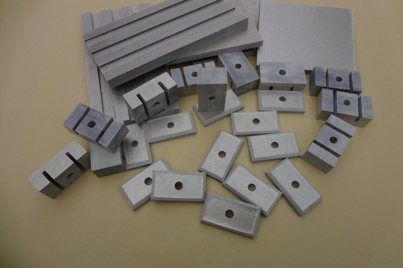
Match the material construction to the way the finished component will be used.
Main Benefits of Commutator Mica Plates
Where This Construction Fits

Brushed DC motor commutators
Segment mica electrically separates neighbouring copper bars. Selection considers both the electrical duty and the mechanical conditions of the rotating assembly.

Traction and industrial motor assemblies
Where a commutator is part of the motor design, duty cycle and thermal class shape the insulation requirement. The application name alone does not determine a suitable plate.
Commutator rebuild and replacement parts
Replacement segments must match the functional geometry and material requirements of the assembly. Similar appearance is not evidence of interchangeability.
Small brushed-motor segments
Small commutators used in appliances and power tools require segment insulation matched to their copper geometry and operating duty. The compact outline does not remove the need for controlled thickness, clean edges and an appropriate bonded construction.
Handling and Assembly Review
Keep the material supported during handling and inspect the finished edges, openings and contact faces before assembly. Review fastening, electrical clearances and heat exposure against the selected construction. A material-level property is not a rating for the complete equipment.
What does commutator mica separate?
Commutator mica electrically separates neighbouring copper segments. The copper carries current, while the mica maintains separation in a stack exposed to clamping, heat and rotation. Thickness and outline also affect the mechanical fit between bars. A material that insulates as a flat sample is therefore not automatically suitable as a finished segment. Review the mica with the copper geometry and assembly process. Distinguish segment insulation from winding wraps or formed rings: these may occur in the same equipment but serve different functions. The location and duty of the component determine which construction should be evaluated.
Is it the same as ordinary heater mica?
It should not be treated as the same material without a proper comparison. Ordinary heater mica is selected for its role in a heating assembly, whereas commutator segment plate must also suit controlled separation, compression and the geometry of a rotating copper stack. Both may contain mica, but the binder, curing state and finished thickness behaviour can differ. Start with the commutator’s material and dimensional requirements rather than choosing a heater sheet that looks similar. Compare the complete construction and inspect the segment after the intended cutting or finishing process. A high advertised heat resistance does not establish that the plate will retain the required fit under assembly conditions. Electrical duty, thermal exposure and mechanical behaviour need to be considered together.
Can segment plate use mica paper or splittings?
Yes. Segment insulation can be made using mica paper or mica splittings, depending on the construction. These descriptions identify how the mica phase is arranged, but they do not fully describe the finished plate. Binder, curing, thickness control and processing also influence how the material behaves between the copper bars. When comparing alternatives, identify the complete bonded material rather than assuming that every paper-based plate or every splitting-based plate is interchangeable. Evaluate the properties that matter to the assembly, including thickness consistency, compression response and electrical separation. The comparison should use the finished segment as well as the original sheet, because cutting and thickness finishing can introduce additional differences that are not apparent from the material description alone. This is particularly important when a replacement changes the mica form while retaining the same outline. Matching dimensions makes the parts comparable geometrically, but the material change still needs its own assessment within the intended assembly conditions.
Why is thickness uniformity important?
Thickness uniformity matters because the commutator contains repeated copper and insulation segments. Variation in individual mica pieces can affect local fit and accumulate across the stack, even when each piece appears acceptable by eye. The relevant requirement is therefore more specific than a nominal sheet thickness. Define where thickness is measured, how variation is assessed and which areas contact the copper. Also consider whether the material’s dimensions change through the intended assembly cycle. A uniform loose segment and a consistent assembled stack are related but different checks. Inspect the finished pieces after any thickness-finishing operation, and avoid relying on a single measurement from one corner of a plate to describe the whole batch or the complete commutator geometry.
Does hardness alone identify a suitable plate?
No. Hardness is only one characteristic. A rigid-looking plate may still differ in thickness consistency, binder condition, compression response or electrical performance. The finished segment must fit the copper stack and suit its thermal and mechanical conditions. Compare those requirements together instead of ranking alternatives by hardness alone. Inspect the outline and cut edges as well as the faces, because machining damage can affect a part that feels solid. Start from the specified construction and assembly duty, then use hardness as one consideration within that assessment. It cannot replace checking the complete material and finished component.
Is a flexible mica wrap an equivalent substitute?
No. A flexible mica wrap and a rigid segment plate are designed around different installation roles. A wrap needs to conform to a surface or follow a component’s shape, while segment insulation must fit between copper bars as part of a controlled stack. The binder, reinforcement and curing state that make a wrap easy to install may not provide the required dimensional response in that location. Similar mica content or a comparable appearance does not establish equivalence. Before considering any substitution, identify the original component’s function and compare the complete construction, thickness and assembly behaviour. Bending a sample into position is not a useful demonstration of suitability for a duty in which uniform rigid separation is the central requirement.
Are moulded rings made from the same plate?
Not necessarily. Moulded rings require a material and process that allow the intended shape to be formed, while segment plate is selected for its finished rigid condition between copper bars. A material that can be shaped during a moulding operation may have a different binder state or construction from a fully cured segment sheet. Both components may belong to the same commutator assembly without being interchangeable. Identify the particular part and the way it is manufactured before selecting stock. Compare the ring’s forming requirements separately from the segment’s thickness and compression requirements. Using the same generic mica description for both can hide an important difference in processing, so the material designation should remain connected to the actual component function. Keep descriptions of these components separate in purchasing and inspection records. A shared reference to mica insulation may be convenient, but it can conceal the difference between stock intended to be formed and stock intended to remain a finished rigid segment.
How should the outline be specified?
Specify the outline from the functional geometry of the copper-bar assembly. Define the segment’s width, length, contours and any critical edges relative to features that matter when the parts are stacked. A generic rectangle or stock sheet size does not explain how the finished insulation should fit. Distinguish dimensions used for blank preparation from those required after cutting or finishing, and identify the thickness separately from the profile. The drawing should also make it possible to inspect narrow features and corners where damage could affect fit. Check a representative segment against the intended copper geometry without forcing it into position. This helps reveal whether an apparent material problem is actually an outline, location or finishing issue.
Why evaluate compression response?
Compression response is evaluated because the mica forms part of a loaded segment stack, not a free-standing flat sheet. The material’s dimensional behaviour under the relevant assembly conditions influences how separation and fit are retained. A nominal thickness measured before loading does not describe everything that happens during clamping or subsequent thermal exposure. Identify the loading and conditioning relevant to the commutator rather than applying an unrelated test condition. Compare the complete bonded material, since the mica construction, binder and cure all contribute to its response. The aim is not to select the softest or hardest plate in isolation; it is to understand whether the finished segments behave consistently within the intended assembly and preserve the required geometry.
Can one thermal rating cover every motor?
No. Different motors impose different thermal duties, and a temperature figure without its context cannot define suitability for every commutator. The mica mineral is only part of a bonded segment plate; the binder and curing state also influence behaviour. Continuous operation, short excursions and the temperature experienced during assembly are separate considerations. Compare the selected construction against the relevant motor and process conditions rather than taking a general mineral heat-resistance value as the plate’s operating limit. Also retain the mechanical requirements in the review: a material must remain suitable for the segment stack, not merely survive heat in an unloaded sample. A useful thermal assessment is therefore tied to the complete insulation component and its actual duty. If the available description does not distinguish mineral behaviour from finished-laminate behaviour, it is insufficient for a direct comparison. Treat that distinction as an evidence requirement rather than filling the gap with a temperature borrowed from another mica product.
Can the segments be punched?
Suitable segment constructions can be punched, while others may be better suited to a different cutting or machining method. The choice depends on thickness, material construction, outline and production requirements. A process suitable for a broad uncomplicated segment may not work equally well for a narrow feature or a different laminate. Evaluate the first finished pieces for profile accuracy, chips and separated layers, paying attention to corners and edges that will contact the copper assembly. Thickness finishing, when required, is a separate issue from punching the outline. Do not assume that a clean-looking punched shape automatically meets the thickness requirement or that a method proven on a general mica sheet is established for a commutator segment.
What should be checked before assembly?
Before assembly, check the specified thickness and outline, confirm that functional faces are clean and inspect the edges for chips, cracks or lifted layers. Review the locations that contact the copper bars rather than relying only on the broad appearance of the sheet. The segments should fit the intended geometry without forcing damaged material into place. Where thickness has been finished separately from the outline, verify both operations against their requirements. Keep the material construction identifiable so that similar-looking stock is not mixed without an established comparison. These checks establish the starting condition of the loose parts; they do not replace qualification of the assembled stack, where clamping, heating and the overall geometry introduce additional requirements.
How should a replacement material be compared?
Compare replacements against the original assembly’s requirements, not colour or a supplier’s grade name. Identify construction, binder condition, dimensions and the response needed under compression and heat. Check that the outline matches the copper geometry and that cutting or thickness finishing leaves acceptable edges. Equal nominal thickness does not establish interchangeability. If the construction changes, evaluate that change in the assembly process rather than assuming equivalence from a description. The comparison should show which requirements remain unchanged and how the finished replacement meets them; another manufacturer’s rating is not proof for a different product.
Does mica choice determine the entire commutator performance?
No. Mica is one element of a system that includes copper segments, clamping, geometry and finishing. The insulation must provide the required separation, but it cannot compensate for every mismatch or process issue elsewhere in the assembly. For example, an accurate mica outline still has to fit the copper-bar arrangement, and consistent loose thickness still has to work under the intended assembly conditions. Review these relationships together when selecting or changing material. This also helps avoid attributing every commutator problem to the mica without examining fit and processing. A sound material choice supports the design, while complete performance depends on how the parts are specified, prepared, assembled and evaluated as a unit.
What is the purpose of assembly qualification?
Assembly qualification checks whether the selected segment material remains suitable after it becomes part of the real commutator construction. Loose-part inspection establishes dimensions and initial condition, but the assembly introduces contact, clamping, heating and interactions with the copper bars. The qualification should therefore reflect the relevant process and duty rather than stop at a flat-sheet comparison. Examine whether the required geometry and electrical separation are retained, and relate any change to the material, finished segment and assembly method. This provides a more meaningful basis for acceptance than appearance or a general supplier description. It is also particularly useful when changing construction or replacing an existing material, because the comparison then addresses the actual component function rather than only a similar product label. Use the same component relationships that will exist in production, including the intended copper geometry and segment preparation. A simplified comparison can be informative, but its conclusions should remain limited to what the comparison actually represents.
Let Us Talk Now
Share your material, dimensions, quantity and application. We will review the details with you.