
Rigid Muscovite Mica Sheets
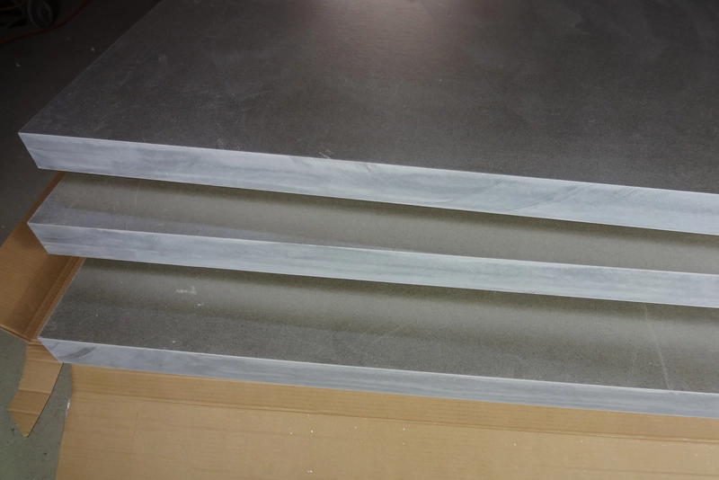
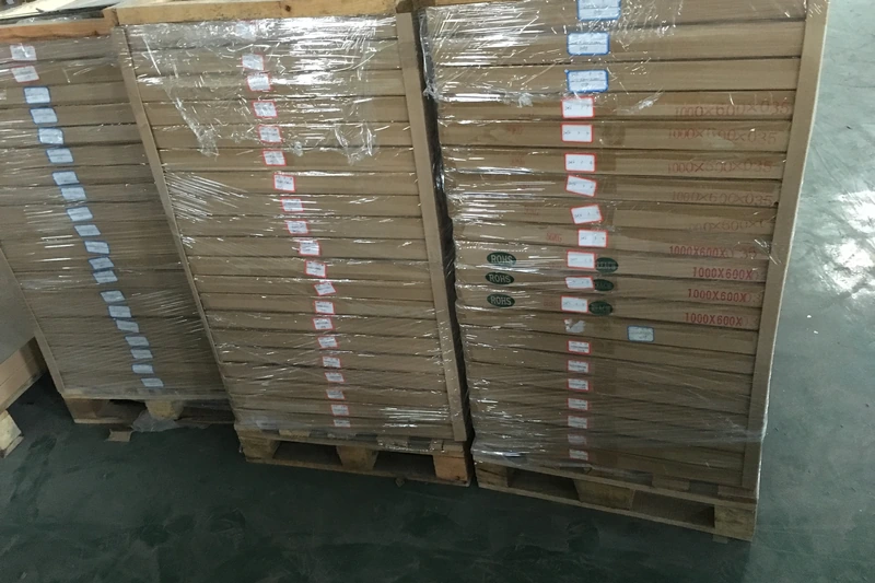
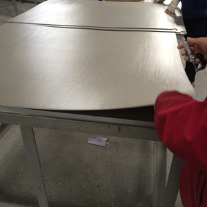
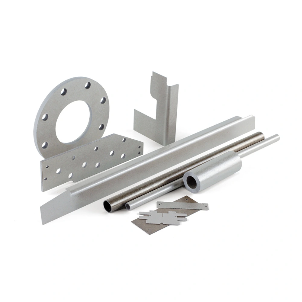
Mica-family material illustration; confirm the exact grade and finished form when enquiring.
Muscovite mica sheets combine electrical isolation and heat resistance in a rigid material for flat components. They are bonded laminates, not individual transparent layers split from a mineral crystal. That distinction makes them relevant to insulating barriers, heater support cards, spacers and other shaped parts whose geometry must remain defined during assembly.
• Material: Rigid Muscovite Mica Sheets
• Format: discuss the required sheet or finished component
• Dimensions: review thickness, outline and fitting features
• Duty: thermal, electrical and mechanical requirements
• Machining: cut profiles, holes and openings by agreement
• Documentation: match the selected construction and application
Format and Dimensional Selection
|
Component format |
Dimensions to define |
Details that affect fit |
Design consideration |
Review evidence |
|---|---|---|---|---|
|
Sheet blank |
Overall length, width and thickness |
Usable area and edge condition |
Allow for the finished profile and the chosen cutting route. |
Finished profile drawing and a usable-area check before cutting. |
|
Insulating strip |
Width, length and thickness |
Straightness and end shape |
Check the supported length rather than treating the strip as a flexible wrap. |
Assembly view showing supports and required end geometry. |
|
Heater support card |
Outer profile, slots and mounting holes |
Hole centres and narrow sections |
Keep the support pattern coordinated with the heating element. |
Element layout aligned with the card’s slots and mounting points. |
|
Washer or spacer |
Outside size, opening and thickness |
Contact faces and hole clearance |
Check the complete stack and its fastening arrangement. |
Stack drawing showing mating faces and the intended opening. |
|
Machined flat part |
Finished drawing and toleranced features |
Datum faces, pockets and cut-outs |
Identify critical fitting dimensions separately from general dimensions. |
Dimensioned drawing with functional datums and inspection features. |
Material Performance and Selection
|
Selection factor |
Muscovite sheet perspective |
What the finished design must address |
Information to review |
|---|---|---|---|
|
Electrical isolation |
A material family commonly selected for dielectric duties. |
Assess operating voltage, temperature and the complete insulation geometry. |
Electrical requirements tied to the actual part geometry and temperature. |
|
Heat exposure |
Useful where heat resistance accompanies electrical insulation. |
Separate sustained operation from short heat peaks; use the selected construction’s rating. |
Exposure description distinguishing sustained operation from heat peaks. |
|
Rigid form |
Suited to a defined flat profile rather than wrapping around a part. |
Support the sheet and avoid forcing a flat laminate into a curve. |
Mounting drawing confirming a flat, supported installation. |
|
Thickness |
Changes the fit, stiffness and insulation path together. |
Choose it from the component duty rather than a generic material comparison. |
Component stack and the consequences of a thickness change. |
|
Binder system |
The laminate contains a bonding system as well as mica. |
Evaluate the finished laminate, not the mineral alone. |
Identification of the finished laminate construction, not just the mineral. |
|
Machined edges |
The layered structure needs controlled cutting and handling. |
Review chips, cracks and separation around holes and narrow features. |
Inspection of fabricated holes, edges and narrow bridges. |
|
Assembly environment |
Heat, moisture, fluids and mechanical loading can act together. |
Validate the material in the intended assembly before a design is released. |
Evaluation conditions representative of the intended assembly. |
Muscovite mica sheets combine electrical isolation and heat resistance in a rigid material for flat components. They are bonded laminates, not individual transparent layers split from a mineral crystal. That distinction makes them relevant to insulating barriers, heater support cards, spacers and other shaped parts whose geometry must remain defined during assembly. The mica provides the material family, while the binder and laminated construction form the usable board. A sheet can therefore be considered both as a starting blank and as the basis of a finished insulating component. Its usefulness comes from matching that form to the equipment: a flat partition beside a conductor has a different job from a flexible wrap around a heater. Identifying the required form early helps keep electrical function, available space and mechanical support aligned throughout the design process.
Material selection begins with the duty of the finished part. Muscovite is commonly evaluated when dielectric performance is important and heat resistance is also needed, but the mineral name does not establish a complete specification. Consider the voltage conditions, temperature at the component, thickness and way the board is supported. A sustained operating temperature is different from a brief heat peak, and an ambient electrical test describes different conditions from a heated assembly. The component’s openings and edges also distinguish it from an uninterrupted material specimen. These considerations help explain why a thicker board or a higher headline test value is not automatically the better choice. Compare candidate constructions on a consistent basis, then review whether the selected sheet suits the actual component rather than transferring a general property of natural mica directly to the laminate.
For a Normanson Mica enquiry, describe the component as it will be used. An outline drawing should show thickness, mounting holes, slots, contact faces and the features that control fit. Clarify whether the requirement is a sheet blank, an insulating strip or a finished profile, because those forms call for different fabrication discussions. Include heat exposure and electrical duty alongside geometry so material choice does not become separated from the application. If replacing an existing part, explain its function instead of relying only on a familiar material label. A drawing-led review can then distinguish essential dimensions from general ones and identify where edge integrity is especially important. This approach creates a practical basis for comparing a suitable rigid construction with flexible mica, higher-heat phlogopite or a more specialised insulating material when the component’s role requires it.
Designing Your Mica Component
A muscovite laminate can provide the starting material for strips, rings, slotted cards and other flat insulating profiles. Choose the fabrication route around thickness and feature geometry. A process appropriate for a simple thin outline does not automatically suit a thicker board with internal openings or narrow bridges.
The drawing should identify mounting holes, contact faces and the dimensions that control fit. Distinguish those features from general dimensions so process planning can focus on the component’s function. Include the intended mounting arrangement when it explains why a particular edge, opening or thickness requires closer attention during fabrication and inspection.
After cutting, review both geometry and laminate condition. Inspect holes, slots and edges for cracking, chipping or separation between layers rather than checking the outline alone. A fabricated trial part also allows the proposed material and shape to be evaluated together in the assembly, where the insulation must perform its intended duty.
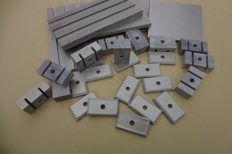
Match the material construction to the way the finished component will be used.
Main Benefits of Muscovite Mica Sheets
Where This Construction Fits
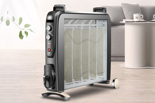
Heating-element supports
Flat cards and spacers can position electrical heating elements while separating them from adjacent conductive parts. The support shape and local heat exposure should be considered together.

Electrical barriers
Use the rigid-sheet format when an assembly needs a defined insulating partition. Openings, mounting positions and the available insulation space remain part of the electrical design.
Washers and flat insulating parts
A shaped mica component can separate contacts or form an insulating layer in an equipment stack. Its mechanical loading and edge condition deserve the same attention as its outline.
Terminal insulation
Flat mica pieces can provide insulating separation around electrical terminals. Define the connection geometry, fastening arrangement and local heat exposure so openings and contact faces are assessed as part of the complete electrical assembly.
Handling and Assembly Review
Keep the material supported during handling and inspect the finished edges, openings and contact faces before assembly. Review fastening, electrical clearances and heat exposure against the selected construction. A material-level property is not a rating for the complete equipment.
What distinguishes a muscovite board from natural mica?
A muscovite board is a manufactured laminate, while natural mica is the mineral from which its insulating constituent originates. Bonding mica into a usable board changes the form being evaluated: the finished product includes a binder and a layered construction, not simply an unaltered mineral sheet. This distinction matters when comparing electrical data, handling behaviour or photographs. A thin piece of natural mica may appear transparent and bend readily, but those features do not describe a rigid bonded board. For a component drawing, identify the required board construction and thickness rather than specifying only muscovite. Assess the finished laminate in its intended flat shape, including its machined edges and mounting arrangement, instead of transferring natural-mineral properties directly to the part.
When is muscovite a sensible starting point?
Muscovite is a sensible material family to evaluate when a component needs electrical separation, a defined flat shape and resistance to heat. The useful starting question is what the finished part must do, rather than whether mica is generally a good insulator. Establish the electrical duty, the temperature at the component and how the board is supported. Then consider the laminate construction and thickness together. A design that must wrap around a curved surface points toward a different form, while unusually severe heat exposure warrants comparison with phlogopite. Muscovite is therefore a starting point for selection, not automatic approval for every electrical assembly.
How does it compare with phlogopite?
Muscovite is commonly considered for dielectric-focused duties, whereas phlogopite is often considered when higher thermal endurance leads the selection. That broad distinction is useful for screening materials, but it does not establish a universal ranking between finished sheets. A laminate’s binder, thickness and construction also influence its performance, and published electrical results may have been measured under different conditions. Compare equivalent product forms first: rigid sheet against rigid sheet, rather than a natural mineral specimen against a bonded board. Next compare the intended temperature, electrical duty and mechanical arrangement. For a heated electrical component, the better choice is the material that meets both requirements in the assembled part. Changing the mineral alone does not prove that an existing thickness, mounting pattern or acceptance test can remain unchanged. For example, a flat electrical barrier and a plate beside an intense heat source may lead to different priorities even if their outlines look similar. Compare the component duties explicitly rather than assuming the mineral choice alone settles both applications.
Can a rigid sheet be wrapped around a heater?
A rigid muscovite board should not be chosen as a wrapping material. It is intended to retain a flat component shape, not to conform around a curved heater during installation. Forcing it to bend can compromise the laminated structure even if the outside surface initially looks acceptable. If the design requires a wrap, curved liner or close conformity to another part, evaluate a purpose-made flexible construction. Do not infer installation flexibility from the word mica or from a photograph of thin natural mica. Choose the material form around the required shape before finalising the insulation arrangement.
How should sheet thickness be selected?
Select thickness as part of the component design, balancing electrical duty, heat transfer, available space and mechanical support. A thicker board changes more than insulation distance: it also changes the fit of the stack, the geometry of holes and slots, and the way the part is held. Conversely, a thin sheet that fits easily may not provide the rigidity the mounting arrangement requires. Start with the assembled drawing and identify where thickness is functionally important, such as between contact faces or beside a heating element. Distinguish that requirement from the overall outline. When comparing candidate sheets, keep construction and operating conditions consistent. Choosing the thickest available material is not a substitute for evaluating the complete insulation path and the finished part’s fit. Check whether a proposed thickness change also requires different mounting hardware or alters the position of the heated or conductive parts. This prevents a material adjustment from creating a separate fit problem elsewhere in the assembly.
Why are operating and peak temperatures different?
An operating temperature describes sustained service, while a peak describes a more limited exposure. The distinction matters because a bonded laminate contains both mica and a binder, and its condition can depend on how long it experiences heat. A headline peak value should therefore not be treated as permission to run continuously at that temperature. Describe the normal duty and any separate heat events, including whether they recur during the equipment’s cycle. Also distinguish the temperature at the mica component from a heater or furnace setting elsewhere in the system. When reviewing a material, look for a rating that matches the actual duration and conditions rather than selecting whichever temperature number is highest. The finished assembly remains the relevant context for approval.
Does a dielectric value define a safe working voltage?
No. A dielectric test value describes a material specimen under stated test conditions; it is not, by itself, a safe working-voltage specification for every component made from that material. The finished part has a particular thickness, edges, holes and mounting arrangement, and it may operate hot rather than at the temperature used for the published test. These details affect how the insulation is used. Treat the material result as one input to the electrical design, not as a direct substitute for assessment of the assembly. In particular, do not simply multiply a quoted value by thickness and assume the resulting number approves the equipment. Compare relevant test conditions and evaluate the finished insulation geometry together with its operating environment and the applicable design requirements. The distinction is particularly important near openings or mounting points, where the geometry differs from an uninterrupted laboratory specimen. Keep a material comparison separate from the equipment approval decision so that a useful test result is not overstated as an assembly guarantee.
What shapes are relevant to this material?
Flat barriers, heater support cards, strips, washers and spacers are relevant starting forms for rigid muscovite sheet. Each uses the material as a defined insulating component rather than a flexible wrap. The outline alone, however, does not establish whether a particular part is suitable. Include thickness, openings and mounting features when assessing the geometry. Identify the dimensions that control fit and the areas where an intact edge is especially important. This helps distinguish a straightforward cut profile from a part that needs more detailed machining and finished-component evaluation. Hole positions and clearances should follow the assembled layout.
Which cutting process should be selected?
Choose the cutting process for the laminate thickness, profile and required finish, not because one method is universally best for mica. Punching or cutting a simple thin outline is a different task from producing slots, holes or detailed features in a thicker board. The layered construction also makes clean edges and freedom from separation important. Begin with the finished drawing, including internal corners, narrow bridges and critical hole positions. Then assess whether the proposed route can produce those features without unacceptable damage. A trial part can help judge the result more directly than the name of the machine or process. Review dimensional fit and edge integrity together; an accurately sized component may still be unsuitable if fabrication has cracked or separated its layers.
What should be inspected after fabrication?
Inspect both geometry and material integrity. The outer length and width are only part of the check: hole locations, slot widths, thickness at relevant contact areas and the features controlling assembly fit also matter. Examine edges, narrow bridges and openings for visible cracking, chipping or separation between layers. These areas can be affected by fabrication even when the main faces appear sound. Use the drawing to distinguish critical features from general dimensions, and relate the inspection to how the component will be mounted. A part should not be accepted solely because it fits inside an outline gauge. Its condition at the places that provide electrical separation or receive fastening loads is equally relevant to the intended insulating function.
Can one board replace every other mica grade?
No. The name mica covers product forms designed for different functions, so it does not establish interchangeability. A rigid electrical sheet, a flexible liner, a thermal board and a commutator plate may share a mineral family while differing in construction and the properties that matter in service. First identify what the existing part does: remain flat, conform to a surface, separate hot areas or fit within a precision component stack. Then compare the relevant material form, thickness and operating conditions. An apparently similar colour or outline is not enough. A replacement needs assessment against the original component’s electrical, thermal and mechanical role rather than a general claim that both materials contain mica.
Does the binder matter in a heat-resistant material?
Yes. The binder helps turn mica into a coherent laminated board, so it belongs in the evaluation of the finished material. Heat resistance stated for the mineral alone does not describe how a bonded component will retain its useful condition during service. Different constructions can use different bonding systems and processing, which is one reason sheets with the same mineral name need not have identical ratings. When comparing materials, look at the laminate as a whole and distinguish sustained heat exposure from a brief peak. The component must also remain suitable after fabrication and within its mounting arrangement. Selecting mica for its thermal properties is reasonable, but excluding the binder from that decision would leave an important part of the product unassessed.
Should the sheet be tested before or after machining?
Material evaluation and finished-part evaluation answer different questions, so both can be useful. Information about the sheet helps establish whether its construction is appropriate for the intended electrical and thermal duty. Machining then introduces the actual edges, holes, slots and contact faces used by the equipment. Those features can reveal issues that are absent from a plain test specimen. A sensible assessment connects the two stages instead of treating either as a complete substitute for the other. Review material information first, inspect the fabricated component, and evaluate it in the relevant mounting arrangement. Where a part operates hot or under mechanical restraint, include those conditions in the assessment rather than relying only on a room-temperature result from an unmachined sheet. This distinction also helps diagnose a problem: unsuitable sheet construction, damage introduced during fabrication and a poor mounting arrangement are different causes. Looking at the material and the completed part provides a clearer basis for deciding which aspect of the design needs attention.
Is rigid muscovite automatically a sealing material?
No. Electrical insulation and sealing are different functions. A rigid muscovite board may provide a flat insulating separation, but that does not establish that it will conform to mating surfaces or behave as required under a sealing load. Mica-based gasket products use constructions selected for that separate purpose. When a component is expected to insulate and seal, define both duties rather than assuming one follows from the other. Consider the joint arrangement, the contact faces and the compression requirement alongside heat exposure. The important question is whether the finished construction suits the joint, not simply whether mica resists heat. A rigid board should not be substituted for a specified gasket without an appropriate material and assembly assessment.
What belongs in a component enquiry?
An effective enquiry describes the part’s function and its finished geometry together. Include the application, outline, thickness, openings and mounting arrangement, then explain the electrical duty and heat exposure. Mark dimensions that control fit, such as a locating hole or the thickness of an insulating stack, separately from less critical overall dimensions. State whether the requested item is a sheet blank or a finished profile so the intended scope is clear. If a part replaces an existing material, describe its role instead of relying only on an old product name. This information allows the proposed construction and fabrication route to be considered together without assuming that a generic muscovite sheet specification automatically covers the complete component.
Let Us Talk Now
Share your material, dimensions, quantity and application. We will review the details with you.