
Punched & Drilled Mica Parts
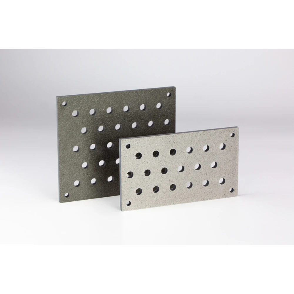
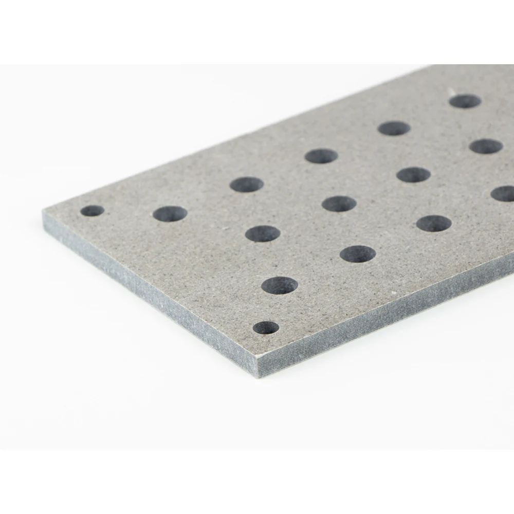
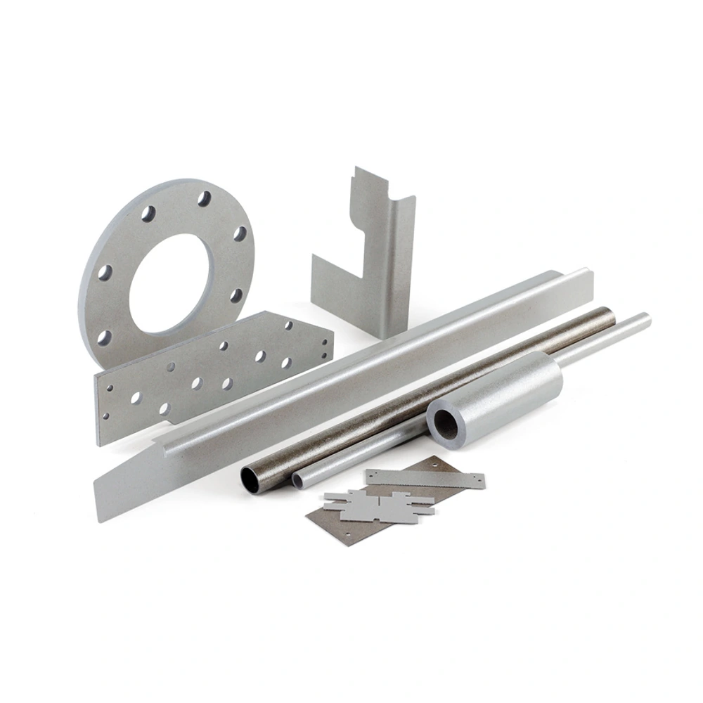
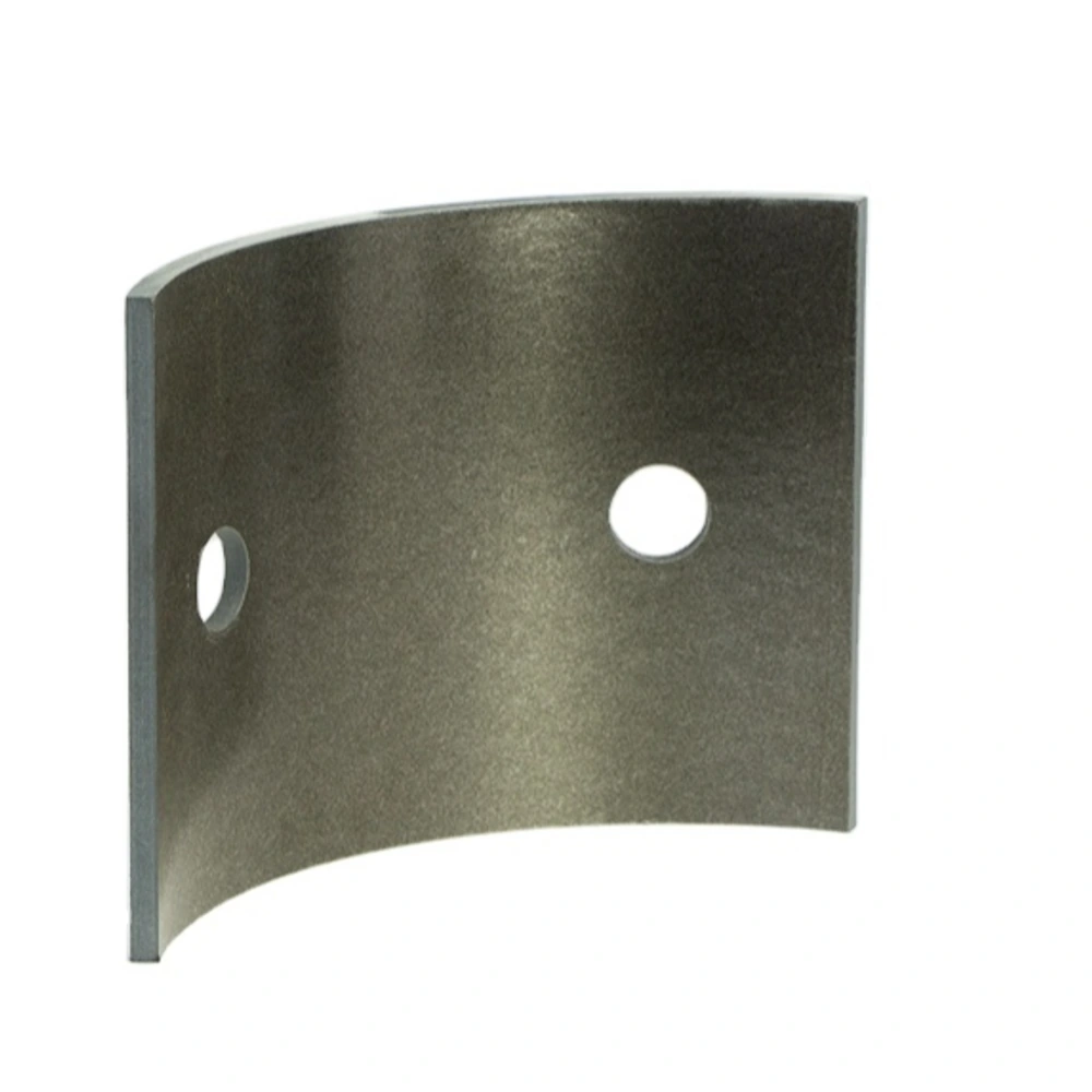
Customer-provided mica component examples. The finished shape, material construction and dimensions are specific to the agreed drawing.
Mica profiles with holes, slots and cut-outs, organized around the finished drawing and the relationship between insulation features and assembly fit.
• Drawing-defined outlines and opening patterns
• Holes, slots and cut-outs reviewed together
• Rigid or flexible construction selected by application
• Critical feature positions clearly identified
• Process route subject to geometry and quantity review
• Edge condition and remaining webs included in acceptance
Feature definition
|
Feature |
Specify |
Review concern |
|---|---|---|
|
Round holes |
Position and opening size |
Alignment with mating parts |
|
Slots |
Length, width and orientation |
Fit and remaining material |
|
Cut-outs |
Profile and reference dimensions |
Clearance and edge condition |
|
Outside contour |
Shape and critical edges |
Assembly envelope |
|
Narrow sections |
Geometry and supported condition |
Handling and process feasibility |
Process discussion inputs
|
Input |
Include |
Outcome to confirm |
|---|---|---|
|
Material |
Construction or application description |
Proposed starting material |
|
Quantity |
Development and repeat-order scope |
Appropriate process proposal |
|
Drawing |
Revision and critical features |
Finished-part requirements |
|
Inspection |
Required checks and records |
Agreed acceptance basis |
Understanding Punched & Drilled Mica Parts
Punched and drilled mica parts turn a sheet or plate into an application-specific insulation profile. The shape may include a simple hole pattern, a series of slots or a combination of openings and outside contours. These features should be specified as a finished component rather than treated as unrelated operations performed on a generic material.
The important relationships are often between features: the distance from a hole to an edge, the location of a slot relative to a mounting point or the material remaining between openings. Identify those relationships on the drawing and explain which ones control fit, separation or support. A visually similar pattern may not serve the same assembly.
The page name describes common processing concepts, not a fixed route for every order. Punching, drilling or another cutting approach may be considered according to the construction, shape and quantity. A drawing-based enquiry allows the finished requirements and a feasible method to be discussed without claiming a universal hole size, tolerance or production capability.
Construction and Order Options
Specify the outside profile and all openings with units, references and revision control. Distinguish round holes from slots or irregular cut-outs, and show any orientation feature that matters during assembly. Where a pattern repeats, define the position clearly rather than relying on a photograph or an informal statement that the holes are evenly spaced.
Consider the starting construction with the intended handling and installation. A rigid profile and a flexible insulation piece can need different support and process decisions even when their outlines match. Include the existing material description if it is known. Otherwise, describe the thermal exposure, electrical duty and mounting arrangement that the proposed part must be assessed against.
Quantity can influence the manufacturing discussion, but it does not remove the need to agree finished-part requirements. State the requested quantity and whether the enquiry concerns a development sample or repeat order. Any tooling proposal, geometry adjustment or inspection limitation should be identified in the quotation before a particular route is accepted.
Application Review
Heating-element cards and insulating profiles can require openings that locate or separate neighboring components. Show the path of the assembly features and the supported areas rather than describing only the outer rectangle. The part must be reviewed with its material and operating conditions, not merely with the number of holes.
In electrical equipment, drilled or cut profiles can form terminal insulation, spacers or barriers around conductors. Feature location and remaining material are relevant to the design discussion. The complete insulation arrangement needs its own assessment; a neat hole pattern does not establish an equipment voltage rating.
For maintenance or development work, combine a controlled drawing with photographs that explain the installation. Identify any proposed changes from an earlier part, including moved openings or revised edge clearances. Keeping those changes explicit helps prevent a process discussion from unintentionally becoming a redesign of a critical insulation feature.
Handling, Fit and Inspection
Support profiles during handling so narrow connecting sections are not used as grips. Inspect hole edges and cut-outs for visible damage before installation. If a part does not align with the assembly, stop and compare the drawing and revision instead of forcing a feature into position or bending a rigid profile.
Any additional on-site drilling or trimming changes the supplied geometry and should be reviewed before it is undertaken. Suitable tools, dust controls and working methods belong to the material and workplace assessment. This product description is not a machining instruction or an authorization to modify a finished insulation component in service.
Agree how the pattern, outline and critical dimensions will be checked. A visual inspection can identify obvious damage but does not replace dimensional verification or required electrical qualification. Keep the acceptance criteria tied to the component drawing so repeat orders can be reviewed against the same defined requirements.
Will every part be both punched and drilled?
No. The title describes a group of mica components with defined openings and profiles, not a mandatory sequence of operations. A particular part may be considered for punching, drilling, another cutting method or a combination, depending on the material and geometry. The enquiry should describe the finished outline, openings and acceptance requirements first. The process proposal can then be reviewed against those requirements and the quantity. This avoids specifying a method merely because it appears in the product name. Any agreed route or limitation belongs in the quotation or manufacturing agreement rather than being assumed to apply to every design in the range.
How should a repeated hole pattern be specified?
Use a controlled drawing with clear units and a consistent reference for the hole positions. State the opening dimensions and show how the pattern relates to the outside contour and mounting features. If certain locations are critical to electrical separation or assembly fit, identify them explicitly. A photograph or the phrase evenly spaced leaves too much room for interpretation, especially when a pattern includes an offset or orientation feature. Include the drawing revision so a repeat order is based on the intended version. Required acceptance limits and the method of checking the pattern should be agreed rather than inferred from a general process description.
Why do narrow sections between openings need attention?
The material remaining between openings forms part of the finished component and can affect handling, support and the process review. A drawing that lists hole sizes but does not make their relationship clear can hide a narrow section that matters in the assembly. Mark these areas and explain whether they are supported or exposed during installation. This does not mean that one universal minimum width applies to all mica constructions. The material, thickness, shape and intended use need to be considered together. Any proposed change to a narrow section should be agreed on the drawing rather than introduced informally during processing.
Can I drill extra holes after receiving the component?
Additional drilling changes the agreed component and may affect its fit or insulating function. Before making a change, review the revised location, nearby edges and remaining material with the equipment requirements. The working method, tools and dust controls also need an appropriate material and workplace assessment. Do not use field modification as a substitute for resolving a drawing mismatch. If an extra opening is needed repeatedly, it is better to document a revised part so future orders can be reviewed consistently. This page describes enquiry information for finished parts and does not provide an approved procedure for drilling mica at the installation site.
Does punching give the same result as machining?
Different routes can produce a similar outline, but the choice should be assessed against the material, geometry and required acceptance criteria. The name of a process does not guarantee that every edge, opening or dimensional relationship will meet the same requirement. For an enquiry, identify the finished features that matter and the quantity being considered. A process proposal can then explain how the requirements will be addressed and whether any changes need agreement. Do not choose solely from a photograph of a similar component or from another supplier’s stated capabilities. The relevant result is the agreed finished part, not a generic preference for one method.
What should be included in a repeat-order enquiry?
Include the part reference, current drawing revision, material requirement and quantity, even if the component has been supplied previously. State whether the design and service conditions are unchanged. If a previous batch revealed an assembly issue, describe the affected feature and distinguish a dimensional concern from damage or an equipment change. Identify any inspection records required for the new order. A repeat shape should not silently inherit an obsolete drawing or an unconfirmed material substitution. Keeping the order tied to a controlled definition helps the process and acceptance review remain consistent without promising a particular lead time or production route before the enquiry is checked.
Let Us Talk Now
Share your material, dimensions, quantity and application. We will review the details with you.