
Curved Mica Insulation Parts
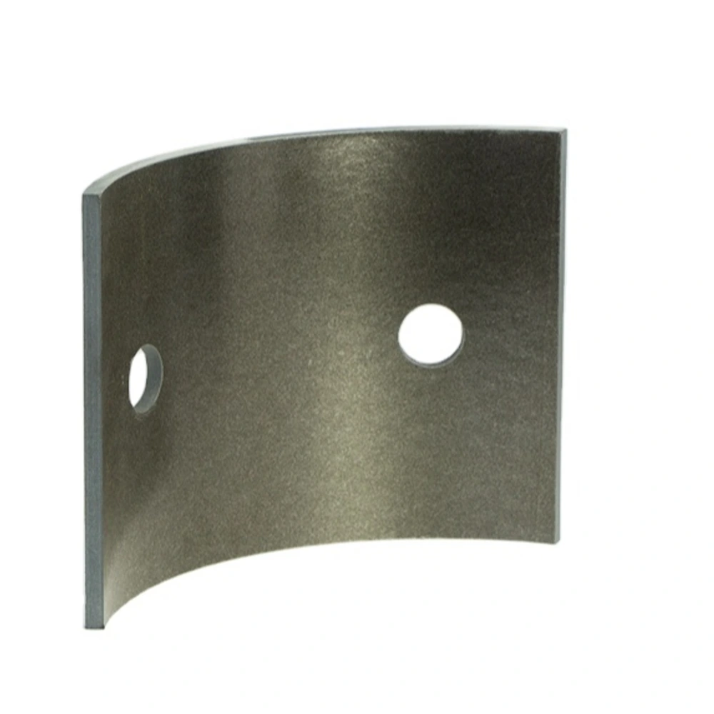

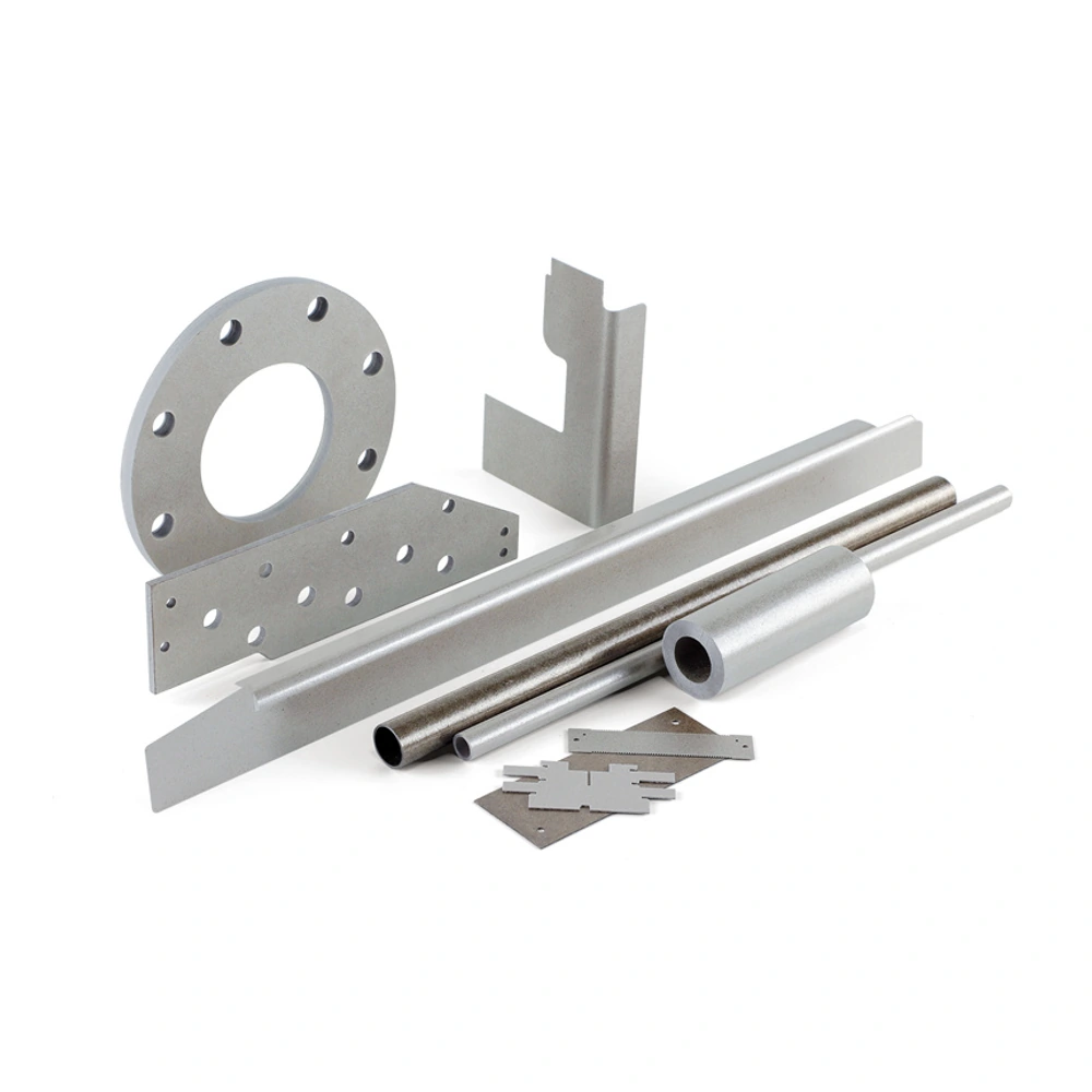
Customer-provided mica component examples. The finished shape, material construction and dimensions are specific to the agreed drawing.
Arc-shaped and contoured mica insulation enquiries, with the free shape, installed shape and material construction defined before a manufacturing route is agreed.
• Flat arcs and three-dimensional contours distinguished
• Section views used to define curvature
• Installed support and orientation included
• Material construction reviewed with the shape
• Drawing-based feasibility rather than universal bend claims
• No fixed forming radius or tolerance implied
Define the curved shape
|
Requirement |
Describe |
Reason |
|---|---|---|
|
Geometry type |
Flat arc or three-dimensional contour |
Prevents shape ambiguity |
|
Reference surface |
Inner, outer or specified datum |
Clarifies curved dimensions |
|
Condition |
Free and installed shapes |
Explains support requirements |
|
Openings |
Location relative to the contour |
Controls orientation and fit |
|
Assembly |
Adjacent segments and mating surfaces |
Defines the complete interface |
Feasibility review boundaries
|
Topic |
Review input |
Confirmation needed |
|---|---|---|
|
Material |
Construction or operating conditions |
Suitable candidate for the defined duty |
|
Shape |
Sections and contour details |
Feasible geometry and process |
|
Fit |
Mating dimensions and support |
Agreed inspection condition |
|
Order |
Quantity and required records |
Specific quotation scope |
Understanding Curved Mica Insulation Parts
Curved mica insulation parts cover shapes that cannot be understood from an outside outline alone. An arc cut from flat plate remains flat through its thickness, while a formed or contoured component has a different three-dimensional shape. A clear section view prevents those cases from being confused and gives the enquiry a meaningful technical starting point.
The desired shape does not determine the manufacturing route on its own. Starting material, rigidity, thickness and the way the part is installed all need review. A flexible insulation construction and a rigid machined arc should not be described as interchangeable simply because both can follow part of a circular assembly in a photograph.
Use this page to describe a curved component for feasibility discussion with Normanson Mica. It does not establish an available forming process, a minimum radius or a guaranteed fit. The geometry, material and any proposed route should be confirmed for the individual enquiry before the design is treated as an agreed supply specification.
Construction and Order Options
Show the curvature in section and identify whether dimensions describe the inner surface, outer surface or another reference. Include the arc extent, thickness, length and any openings that locate the part. Where a contour changes along its length, provide enough views to avoid reducing a three-dimensional requirement to a single ambiguous radius.
Explain whether the supplied shape must remain unsupported or is held against a mating surface after installation. The free condition and installed condition may need separate descriptions. Do not assume that a rigid flat component can be pulled into a curve by its fasteners. Any flexibility or forming requirement belongs in the material and process review.
For segmented concepts, identify the relationship between adjacent pieces and the intended gaps or overlaps. A segmented insulation arrangement is not automatically equivalent to a continuous piece. The assembly drawing should show orientation and support, while the quotation should identify the included components and any geometry changes that require approval.
Application Review
Curved or arc-shaped insulation may be considered where a component follows part of a heater or thermal assembly. Describe the heat-exposed face and the support around the contour. The selected construction needs to be reviewed against those conditions rather than assigned a general temperature capability based on the mica name.
In electrical equipment, an arc or contour may be used as part of an insulating interface around adjacent components. Show the conductors, mounting features and required orientation in an assembly view. Suitability depends on the complete arrangement, and the curved shape alone does not establish electrical separation or equipment compliance.
When replacing an existing curved part, document its condition before measuring. A damaged or deformed sample may not represent the intended free shape. Photographs from several directions, a section sketch and known mating dimensions can support a review, but a controlled geometry definition is still needed before a replacement is ordered.
Handling, Fit and Inspection
Support curved components in a way that does not force their contour to change. Avoid stacking or gripping arrangements that load a narrow edge or opening. Keep orientation and part identification visible where similar segments have different positions. Inspect the edges and surface for damage before bringing the part into the assembly.
Compare the part with the intended mating geometry without using installation force to conceal a mismatch. Bending, heating or trimming a supplied component is a design and process change, not a routine correction described by this page. Resolve any shape discrepancy against the drawing and agreed acceptance method first.
Inspection should explain how curvature and important features are assessed, including whether the part is checked free or supported. A simple overall length may not capture the fit of a contour. Agree the relevant references and records with the quotation, and keep application qualification separate from the dimensional review of the shape.
Is a flat mica arc the same as a curved mica part?
Not necessarily. A flat arc has a curved outline when viewed from above but can remain flat through its thickness. A contoured or formed part changes shape in three dimensions. A single photograph can make these cases look similar, which is why a section view is important. State the intended geometry and identify the surfaces used for dimensions. Also explain how the component sits in the assembly. The distinction affects the material and process review, so it should be resolved before a quotation is based on a general description such as curved mica or an image of a superficially similar part.
Can a rigid mica sheet be bent to the required radius?
That should not be assumed. Rigidity and flexibility describe different constructions and behavior, and a desired radius does not establish that a particular sheet can be bent into it. Define the required contour, thickness and installed support, then review the material and proposed process together. Do not use fastening pressure or on-site heating as an unreviewed way to force a flat component into shape. This page provides an enquiry route for curved geometry, not a forming instruction or a promise of a universal bend capability. Any agreed shaping method and resulting acceptance requirements need to be specific to the component under consideration.
Which dimensions describe a curved component adequately?
The answer depends on the shape, but a useful drawing normally identifies the reference surface, thickness, extent of the arc or contour and the length in the other direction. Openings and locating features should be positioned relative to clear references. If the contour changes, include additional sections or a suitable model rather than relying on one radius. State whether the dimensions apply to the free part or its installed condition. The goal is to make the intended geometry unambiguous, not to impose the same measurement scheme on every component. Critical fit requirements and the inspection condition should then be agreed during the drawing review.
Can a curved part be supplied as several segments?
A segmented version can be submitted for review, but it is a design choice rather than an automatic equivalent to a continuous component. Show how the segments are positioned, supported and joined in the assembly, including any intended gaps or overlaps. Identify whether each segment is identical or has a separate orientation and reference. The insulation function must be considered across the complete arrangement, not only within one piece. Material and process feasibility should be checked against that drawing. The quotation should make the included parts and any agreed changes clear without assuming a particular segment size, forming route or installation method from the product category.
How should curvature be inspected?
The inspection method should reflect the way the geometry is defined and used. First establish whether the part is assessed in its free condition or against a specified support. Identify the reference surfaces and the features that control fit, rather than relying only on overall length or a visual comparison. The drawing and quotation should record the acceptance basis and any required inspection information. A photograph can help show the condition of a part but cannot establish a precise contour on its own. Dimensional acceptance also remains separate from the electrical or thermal qualification of the completed assembly in which the curved component will operate.
What if only an old curved component is available?
Use it as supporting evidence, but first record any cracking, distortion or wear that could affect the measured shape. Take photographs from several directions and identify the surfaces that mate with the equipment. Where possible, compare the sample with known dimensions of the surrounding assembly or an earlier drawing. Distinguish confirmed measurements from estimates and explain whether the sample was measured free or restrained. This information can support a drawing review without treating a damaged part as an exact design master. Material identity and service suitability still need separate consideration; neither can be established reliably from the visible curve or surface color alone.
Let Us Talk Now
Share your material, dimensions, quantity and application. We will review the details with you.