
Mica Flanges
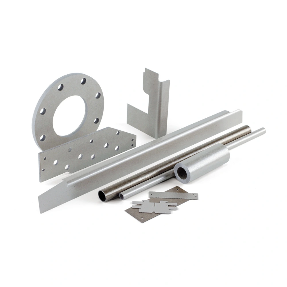
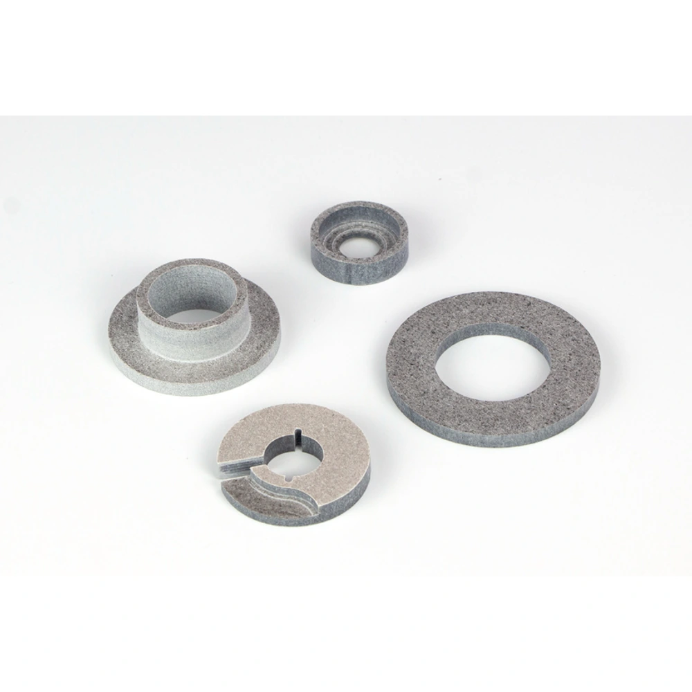
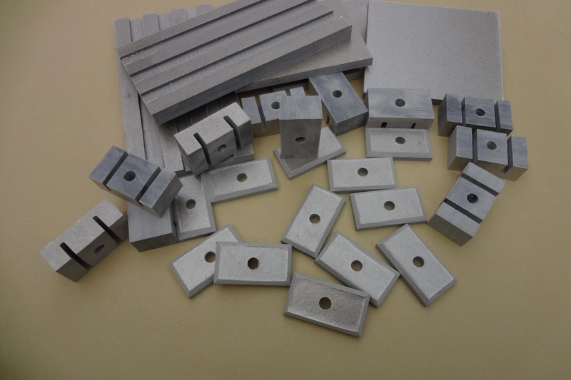
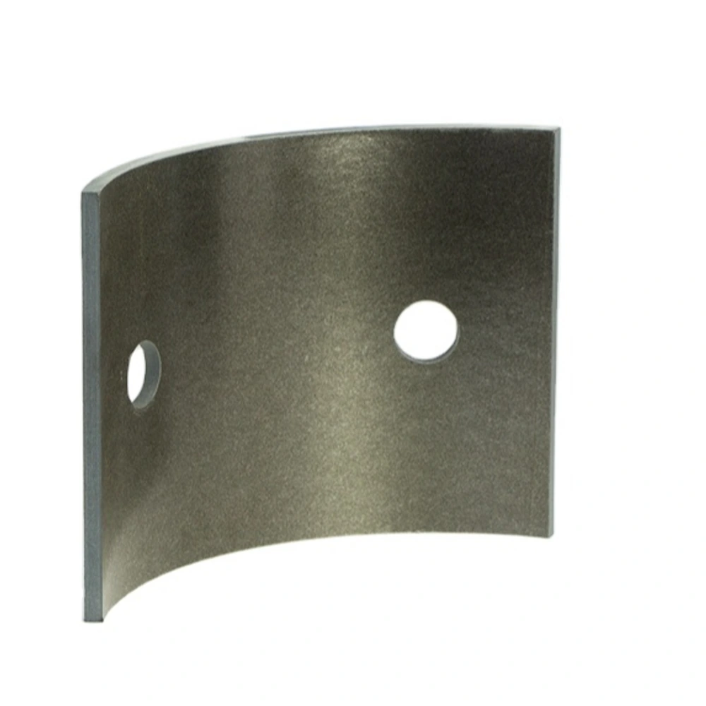
Customer-provided mica component examples. The finished shape, material construction and dimensions are specific to the agreed drawing.
Drawing-defined mica flange shapes for insulating interfaces, with mating faces, openings and mounting features reviewed as a complete component.
• Annular and shaped flange enquiries
• Mounting pattern defined on a controlled drawing
• Mating faces and supported areas identified
• Material selected with the operating conditions
• Segmented or stepped designs subject to review
• No general pressure or structural rating implied
Flange drawing information
|
Feature |
Required description |
Review purpose |
|---|---|---|
|
Mating faces |
Contact and supported areas |
Interface fit |
|
Opening |
Profile and location |
Clearance around adjacent parts |
|
Mounting pattern |
Hole positions and orientation |
Assembly alignment |
|
Section |
Thickness and any steps |
Shape and process review |
|
Function |
Insulation, spacing or other defined duty |
Avoids assuming pressure capability |
Application review checklist
|
Topic |
Useful information |
Do not assume |
|---|---|---|
|
Material |
Existing specification or duty description |
Equivalent performance from color |
|
Fastening |
Assembly view and contact arrangement |
A universal tightening value |
|
Heat |
Exposed face and service history |
One rating for all constructions |
|
Acceptance |
Critical features and inspection basis |
A general tolerance for all dimensions |
Understanding Mica Flanges
A mica flange is an insulation component defined by its interface with surrounding equipment. It may resemble a ring, a shaped plate or a part with a mounting pattern, but the word flange does not establish a standard geometry. The drawing needs to show how the part locates, which faces make contact and what must remain electrically separated.
This page concerns insulating flange-shaped parts, not a universal substitute for structural or pressure-rated metal flanges. A flange can carry several functions in an assembly, and these should be separated clearly in the enquiry. Explain whether the mica part provides an insulating interface, a spacer or another defined role, and identify any additional validation the equipment requires.
Material and shape must be considered together. A broad flat ring, a narrow annulus with closely spaced holes and a stepped profile present different questions for support and processing. Normanson Mica can review enquiries against the supplied drawing; the final material, geometry and order scope require confirmation rather than being inferred from a sample photograph.
Construction and Order Options
Show the central opening, outside outline and mounting holes from a consistent reference. Include any orientation feature that prevents the flange being installed incorrectly. If the interface is not circular, define the profile directly rather than describing it through a nominal diameter. The relationship between holes and contact faces should remain clear in both the drawing and assembly view.
For stepped or segmented concepts, provide section views and explain how the pieces are supported. A visible step does not establish how the part should be manufactured, and a split design can change the way the interface is assembled. Process feasibility and any suggested geometry changes should be reviewed before an order is based on the drawing.
Describe the actual thermal and electrical conditions, along with the fastening arrangement. If a known material specification applies, supply it without assuming that another mica construction is equivalent. If the material is still under review, identify the function and constraints so the discussion can focus on selection rather than on an unsupported rating or material substitution.
Application Review
In thermal equipment, a flange-shaped component may create an insulating interface around an opening or mounting location. Show the hot side, surrounding surfaces and any areas that remain unsupported. The useful specification combines the interface geometry with the thermal exposure rather than assigning a single temperature limit to every flange shape.
In electrical assemblies, annular or profiled interfaces can be considered where conductive components require separation. The opening, fastener positions and neighboring conductors should be visible in the assembly information. Selection must address the completed interface, not only the insulation characteristics associated with a starting sheet.
For replacement flanges, compare the existing part with the equipment drawing and identify wear, cracking or assembly changes. Photographs can help explain orientation and damage. They should supplement measurements and a controlled revision, especially when a damaged hole or distorted contact face might otherwise be mistaken for the original geometry.
Handling, Fit and Inspection
Support the flange during storage and movement, particularly where a large opening leaves a narrow ring. Avoid using a mounting hole as a lifting point or forcing the part into alignment. Check the outline and openings before installation so a fit problem is resolved without stressing the mica component.
Installation should follow the equipment’s approved joint arrangement. Mating surfaces, fastening sequence and applied loading are design matters and are not specified by this general product page. Do not treat a dimensional fit as evidence that a flange is suitable for pressure containment or for carrying an unreviewed structural load.
Agree inspection priorities before ordering. Common discussion points include the mounting pattern, opening position, thickness and visible condition of contact faces. Record any special acceptance requirement on the drawing or order. If the component has an additional sealing or safety-related duty, its validation needs a separate documented basis.
What does mica flange mean in this range?
It means a drawing-defined insulation component with a flange-like interface, such as an annular plate or a shaped part with mounting features. It does not identify one standardized product or prove a pressure rating. The most useful description shows the opening, contact faces, fastening pattern and the parts that need separation. If your assembly uses the word flange for a different shape, include a drawing and explain its function. The enquiry can then be reviewed against the actual component rather than the name alone. Structural support, sealing and electrical insulation are distinct requirements and should be stated separately where more than one applies.
Can a mica flange replace a metal flange?
A direct substitution should not be assumed. A metal flange may locate parts, distribute fastening loads, contain pressure or perform several functions at once. A mica insulation component must be assessed against the specific duty assigned to it in the proposed assembly. Matching the outside shape and mounting pattern is only one part of that assessment. Provide the original arrangement, the reason for substitution and the operating conditions. The review should identify which functions remain with the metal hardware and which are intended for the mica part, with any necessary testing agreed before the revised design is treated as suitable for service.
Which drawing views are most useful?
A plan view defines the opening, outline and mounting pattern, while a section view explains thickness, steps and contact faces. An assembly view is valuable when the flange is partly supported, sits between several materials or requires a particular orientation. Use consistent units and a clear drawing revision. Mark the dimensions that control fit instead of applying an unsupported blanket tolerance to all features. If a sample is used, distinguish measured dimensions from estimated ones and note any damage. These views help separate the intended finished geometry from assumptions about how the part should be produced or fitted into the equipment.
Are split or segmented flange shapes possible?
They can be submitted as drawing-based enquiries, but feasibility is not established by the product category. Explain why the flange is split and how the segments are located and supported after installation. Show the segment interfaces, mounting features and any required gaps on a controlled drawing. A segmented design can change assembly access and the continuity of the insulating interface, so it should not be treated as identical to a one-piece ring. The material and proposed process need review with those details. Any geometry adjustment or limitation should be confirmed before the enquiry becomes an order for a specific component.
How should flange thickness be selected?
Thickness should follow the interface and material requirements of the assembly rather than a general rule for all mica flanges. It can affect spacing, fit, support and the available geometry around openings. The thermal and electrical duty also needs to be considered with the selected construction. If an existing drawing specifies thickness, include that requirement and its acceptance basis. If the design is still developing, describe the available space and the role of the component. A review can then address the choice without presenting another supplier’s standard range or a material data-sheet value as a guaranteed solution for your flange.
What must be confirmed before installation?
Confirm that the part identification, material description and drawing revision match the intended assembly. Check the opening and mounting pattern without forcing the flange into place, and inspect contact faces and edges for visible damage. The mating surfaces and fastening procedure should follow the equipment design, including any agreed loading or sealing requirements. Do not use tightening to compensate for an incorrect fit. If the flange has a pressure, structural or other safety-related duty, make sure the separate validation for that duty has been addressed. A successful dimensional check alone does not establish the performance of the completed joint in operation.
Let Us Talk Now
Share your material, dimensions, quantity and application. We will review the details with you.