
Mica Tubes
Rigid tubular insulation selected around the component, its heat exposure and its electrical duty.
Mica Tubes for Industrial Insulation
Mica tubes provide an insulating form around cylindrical components. A finished tube combines mica with a bonding system and a defined wall, making its inside diameter, outside diameter and length relevant to the assembly. It is not simply a rolled version of any flat mica sheet.
This range has two material-led routes, muscovite and phlogopite, plus an application-led route for insulating sleeves. A sleeve can use either mineral. These pages therefore describe overlapping selection dimensions, not three unrelated substances or automatically interchangeable grades.
Use the material pages when choosing the construction for electrical and thermal duty. Use the sleeve page when bore fit, end position and the finished insulating length lead the enquiry. Both routes should converge on the same component drawing and operating conditions.
Mica Tubes Specification & Selection
Choose the right enquiry route
|
Route |
Primary question |
Relationship |
|---|---|---|
|
Muscovite mica tubes |
Is electrical duty the main selection priority? |
Material route; can also be supplied as a sleeve form. |
|
Phlogopite mica tubes |
Does higher thermal exposure drive selection? |
Material route; binder and component conditions still matter. |
|
Mica insulating sleeves |
How must the finished insulating part fit? |
Form and application route; mineral remains a separate choice. |
Define the tube as a component
|
Feature |
Information to define |
Why it matters |
|---|---|---|
|
Inside diameter |
Bore and the member it surrounds |
Establishes the inner fit. |
|
Outside diameter |
Available envelope and adjacent parts |
Establishes clearance to the surrounding assembly. |
|
Length and ends |
Insulating span and end positions |
Connects the tube to its mounting arrangement. |
|
Wall construction |
Mineral, binder and wall geometry |
Describes the finished product rather than raw mica. |
|
Operating duty |
Heat exposure, electrical separation and support |
Connects material selection to the complete component. |
Start with the part being insulated and the available space around it. Define the bore, outside envelope and length together, then identify where the tube is supported. A wall description should remain consistent with both diameters rather than being considered independently.
Next separate sustained heat exposure from short events and identify the temperature at the tube rather than only the equipment setting. Muscovite and phlogopite offer different material starting points, but the binder and finished construction remain part of the decision.
Finally review electrical separation, mounting and fabrication as one arrangement. A correctly sized tube is not automatically an approved insulator for every application. The tables below organise component requirements without presenting another manufacturer’s dimensions, tolerances or laboratory values as a Normanson guarantee.
Heated electrical components
Tubular insulation can surround parts near heating elements. Consider the local exposure and neighbouring contact surfaces together.
Rod and terminal insulation
A sleeve can separate a cylindrical member from surrounding equipment. Bore clearance, insulating length and end position belong in the drawing.
Coil and core assemblies
Tube geometry may provide a defined insulating boundary around a core or related component. Selection remains specific to the assembly.
Build a Clear Enquiry
Identify the required product, drawing revision, material construction, dimensions and quantity. Include the intended electrical, thermal and mechanical duty and the documents needed for acceptance. Final supply details belong to the reviewed quotation and order specification.
Explore Mica Tubes
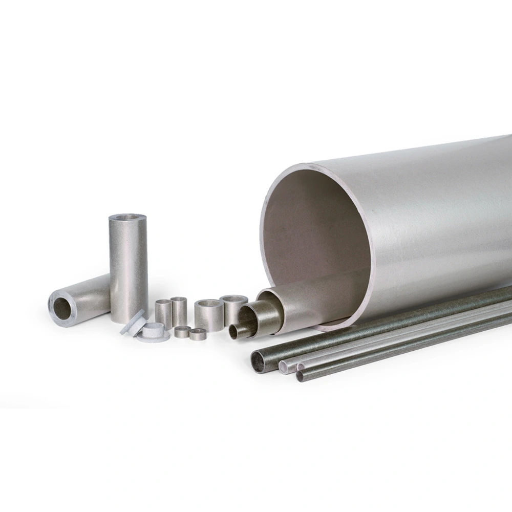
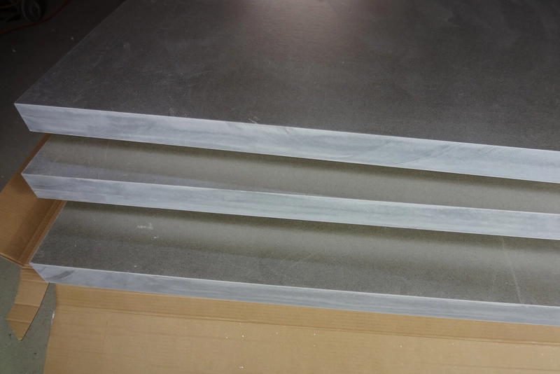
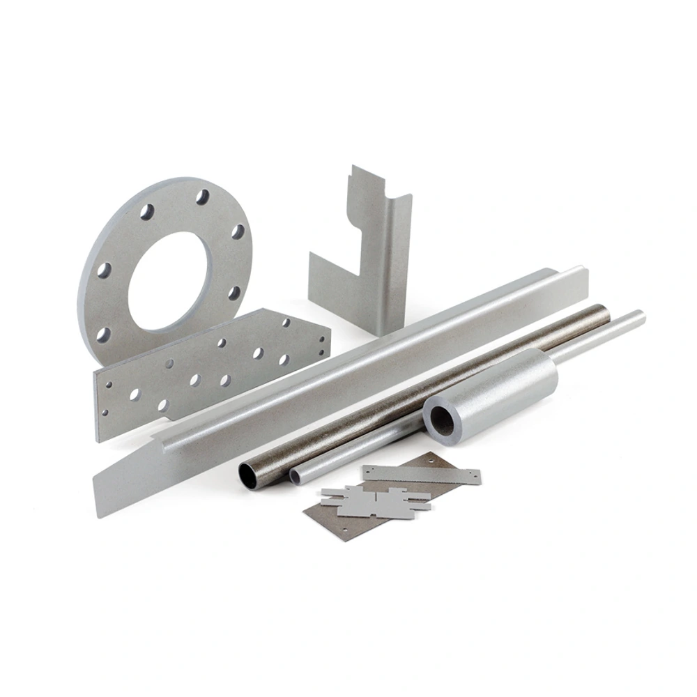
Customer-provided product-family photographs. Mineral grade, binder and reinforcement cannot be confirmed from appearance alone.
Materials, Dimensions & Technical Review
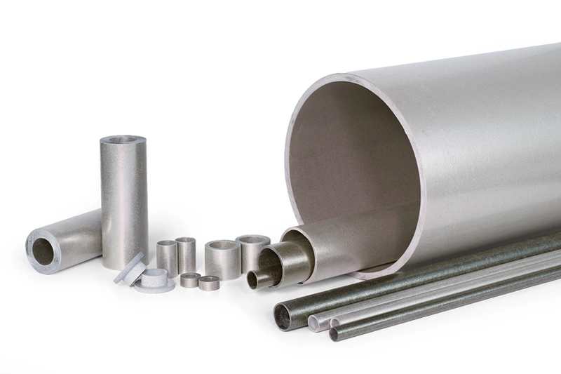
Material & Component Review
Define bore, outside diameter and length together. Identify the supporting surfaces and required fit before selecting the tube.
Compare sustained and short-term heat exposure at the component. Mineral type, binder and construction all affect selection.
Review electrical separation, mounting and finished dimensions together. Confirm the proposed material and inspection requirements for the actual assembly.
Match the Product Form to Your Requirements
Muscovite Mica Tubes: Rigid tubular insulation for electrically focused cylindrical components.
Phlogopite Mica Tubes: Tubular insulation considered where heat exposure leads material selection.
Mica Insulating Sleeves: Finished tubes matched to bore fit, insulating span and assembly interfaces.
Application Examples
Heated electrical components 
Rod and terminal insulation 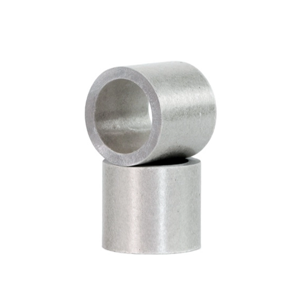
Coil and core assemblies
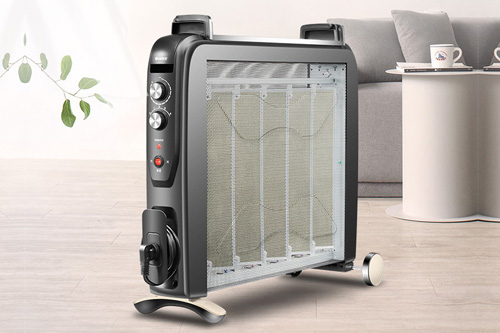
Heated electrical components
Tubular insulation can surround parts near heating elements. Consider the local exposure and neighbouring contact surfaces together.
Rod and terminal insulation
A sleeve can separate a cylindrical member from surrounding equipment. Bore clearance, insulating length and end position belong in the drawing.
Coil and core assemblies
Tube geometry may provide a defined insulating boundary around a core or related component. Selection remains specific to the assembly.
Related Materials and Drawing-Based Support
Frequently Asked Questions
Discuss Your Mica Tubes Requirements
Send the product form, dimensions, quantity and operating conditions. Let us review a suitable construction for your application.