
Mica Insulating Sleeves
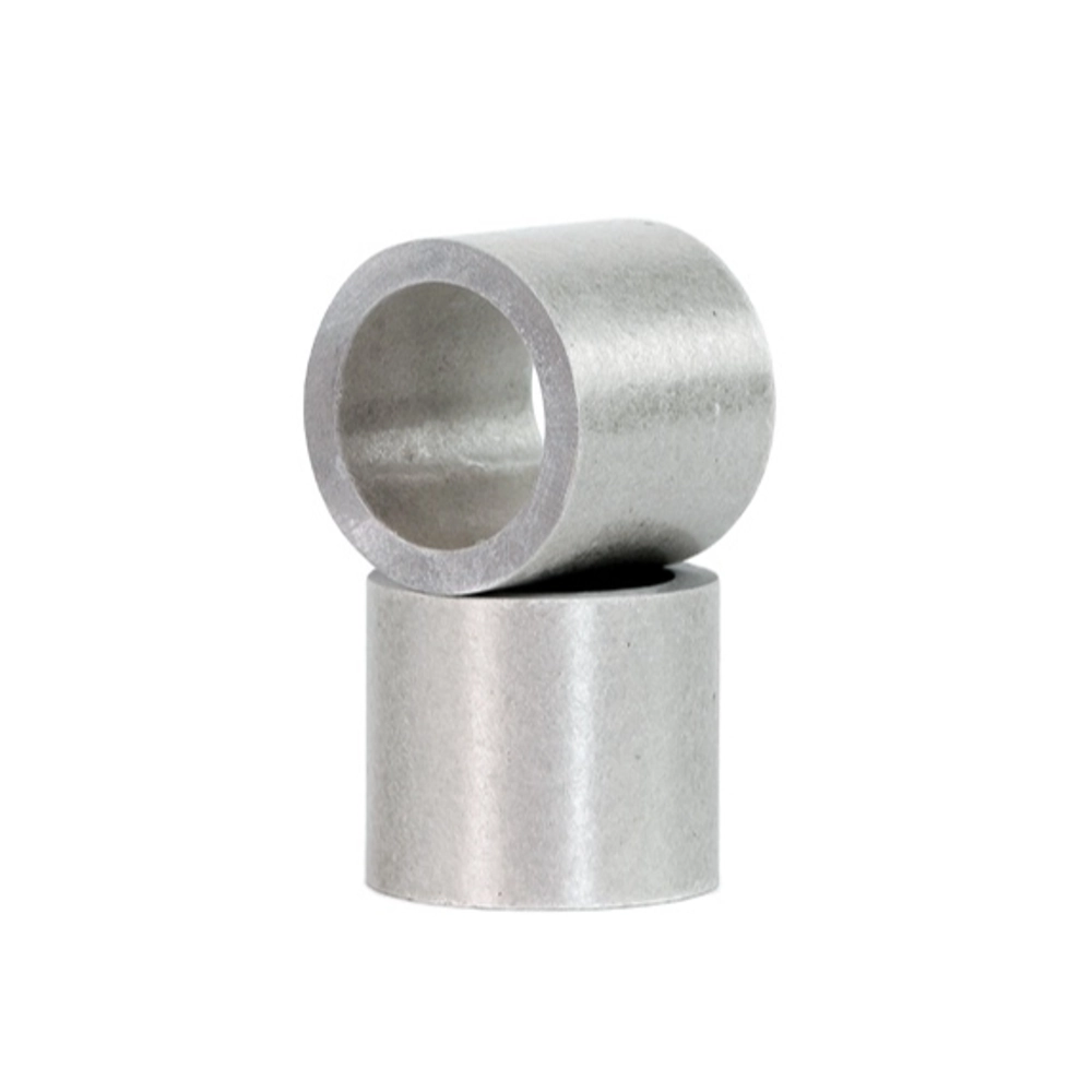
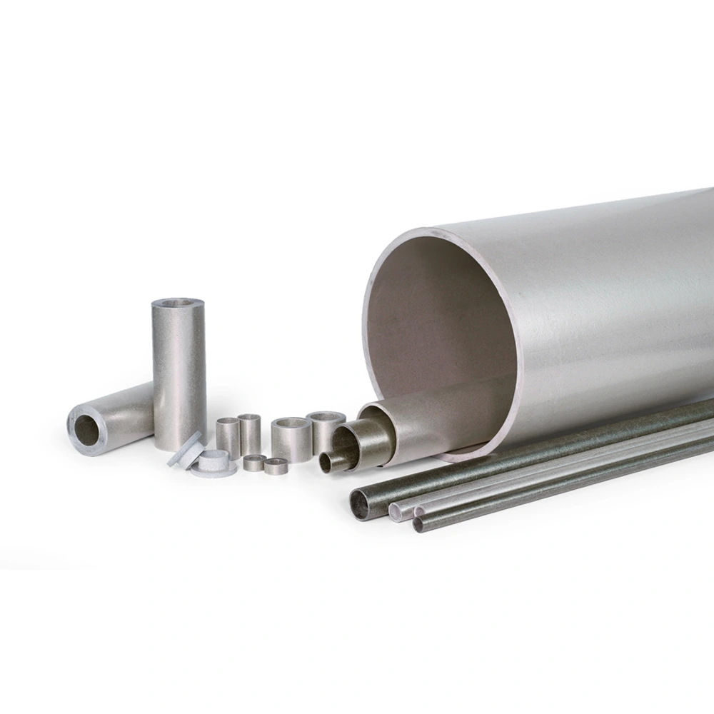
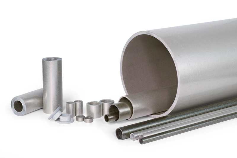
Customer-provided product-family photographs. Mineral grade, binder and reinforcement cannot be confirmed from appearance alone.
Finished tubular mica parts selected around bore fit, insulating span and the assembly interface.
• Finished-part and application-led route
• Muscovite or phlogopite remains a separate choice
• Bore and outside clearance defined together
• Length connected to the required insulating span
• Ends reviewed as functional interfaces
• No automatic equivalence to flexible sleeving
Sleeve drawing essentials
|
Interface |
Describe |
Reason |
|---|---|---|
|
Inner |
Bore and enclosed member |
Defines the required inner fit. |
|
Outer |
Available envelope and locating surfaces |
Connects the part to surrounding equipment. |
|
Ends |
Finished length and positions |
Defines the insulating span. |
|
Material |
Mineral and bonding construction |
Separates form from material choice. |
Avoid false equivalence
|
Similar description |
Difference to review |
Useful check |
|---|---|---|
|
Two sleeves with matching size |
Mineral or binder may differ |
Compare the actual construction. |
|
Tube and finished sleeve |
End position and fit may differ |
Use the installed component drawing. |
|
Rigid and flexible sleeving |
Installation behaviour differs |
Do not rely on stretching or conformity. |
|
Existing and replacement part |
Duty may not be captured by appearance |
Review electrical, thermal and mounting conditions. |
Understanding Mica Insulating Sleeves
A mica insulating sleeve is a tubular part used around a cylindrical member to provide a defined insulating boundary. Sleeve describes the component’s form and job, not a separate mica mineral. This page therefore begins with fit and assembly: what the part surrounds, where it ends and how it relates to neighbouring components.
A sleeve may use muscovite or phlogopite construction according to the electrical and thermal duty. The mineral and bonding system should be identified independently of the finished shape. Two sleeves with similar dimensions can have different constructions, while two tubes with the same material may be finished to different lengths or interfaces for different equipment.
The useful distinction is between a general tube enquiry and a finished sleeve requirement. A sleeve drawing connects the bore, outside envelope and insulating span to a specific assembly. It should not be confused with flexible fabric sleeving or assumed to conform under installation pressure simply because it surrounds another part.
Construction and Order Options
The bore establishes the relationship with the enclosed member. Define the intended fit rather than describing only an approximate diameter. Then identify the outside space available and any surfaces that position the sleeve. These relationships help avoid selecting a part that matches the inner member but conflicts with the surrounding assembly.
Finished length and end position determine the span covered by the sleeve. An end may locate against another part or sit beside an exposed interface, so the drawing should show more than a free-standing tube. Treat the ends as functional features where relevant, without assuming an unverified finish or machining tolerance.
Choose the mica construction around actual service conditions. The term sleeve does not decide whether muscovite, phlogopite or another construction is appropriate. Describe electrical separation, heat exposure and mechanical support together, and distinguish ordinary operation from separate heat events when comparing candidate materials for the finished component.
Application Review
Rod insulation is an application-led starting point for a sleeve. A defined tubular part can separate the member from surrounding equipment, provided its construction and geometry suit the duty. Bore fit and insulating length should be considered with the contact arrangement rather than copied from an unrelated tube size.
Terminal and connection assemblies may use a short tubular insulating part where a cylindrical member passes through or sits beside other components. The relevant drawing identifies the inner and outer interfaces and the positions of the ends. A sleeve name alone does not establish electrical clearance or suitability for a particular connection.
Heater-related sleeves can provide a cylindrical insulating form near heated components. Here the local exposure and the selected mica/binder construction belong alongside the fit requirements. The sleeve should be evaluated as a component of the heated assembly, not described as guaranteeing the thermal or electrical rating of the complete equipment.
Handling, Fit and Inspection
Before installation, compare the sleeve with the component drawing and the actual interfaces it must fit. A rigid mica sleeve is not a flexible cover that can be stretched into position. An unsuitable bore or outside envelope should be resolved through the component specification rather than compensated for by force during assembly.
Inspect the ends, bore and outer surface where they matter to location or insulation. Visible edge damage, cracking or separation can be relevant even if the nominal dimensions appear correct. The inspection should reflect the finished sleeve’s function instead of treating it as an undifferentiated piece of tube stock.
For replacement work, retain both material and geometric information from the existing duty. A matching length and diameter do not prove construction equivalence. A representative fitted sample can assist review, but electrical and thermal suitability still need to be considered under the intended service conditions before the component is accepted.
Is a sleeve a third mineral type?
No. Sleeve describes the finished tubular form or its role around a component, whereas muscovite and phlogopite identify mica mineral routes. A sleeve can therefore use either construction when appropriate for its duty. This page focuses on bore fit, insulating length, end position and the interfaces within an assembly. Material selection remains a separate but connected decision. The distinction prevents the catalogue from implying that sleeves are unrelated to tubes or automatically interchangeable with them. A complete enquiry should identify both the finished geometry and the intended mica/binder construction, or explain which material question still needs evaluation for the operating conditions. This overlap is intentional in the catalogue: it gives buyers a material-led route and a component-led route to the same kind of enquiry. It should not lead to duplicated assumptions about stock or ratings. The sleeve page adds assembly context, while the mineral page helps organise the material comparison.
How does a sleeve enquiry differ from a tube-stock enquiry?
A sleeve enquiry usually centres on a finished component within an assembly rather than only a general tubular material form. Its length, bore, outside envelope and end positions are tied to the member being insulated and nearby parts. A tube-stock description may not capture those relationships. Provide the installed drawing and identify which surfaces locate the sleeve or control fit. Keep the required material construction attached to that geometry rather than assuming the word sleeve specifies it. This makes the enquiry useful for component review while avoiding unsupported assumptions about stock sizes, finish, tolerances or suitability of a tube that merely has a similar nominal diameter.
Can rigid mica sleeves stretch to fit?
A rigid mica sleeve should not be treated as a stretchable or conformable cover. Its bore and outside dimensions need to suit the assembly as specified. The fact that other insulating sleeves may be flexible does not establish the same behaviour for a bonded mica tube. Before installation, compare the component interfaces with the drawing and inspect the material for visible damage. If the fit is unsuitable, resolve the dimensional or material requirement rather than using force to make it conform. This keeps the distinction between a rigid finished component and a flexible wrapping product clear, which is important for both mechanical fit and the intended insulating function.
Why are sleeve ends important?
The ends establish where the insulating span starts and finishes, and they may also locate the part within a stack or against another component. Their role therefore depends on the assembly, not simply the overall tube length. A drawing should show the relevant neighbouring parts and identify whether an end is a functional locating surface or an exposed boundary. Inspect those areas for visible damage as well as checking the length. A sleeve that matches the bore but ends in the wrong position may not serve the intended role. Geometry and electrical function should therefore be reviewed together rather than treating the ends as incidental cut surfaces. For a replacement, compare the installed start and finish of the insulating span rather than relying only on a loose part measurement. The relationship to adjoining components explains why a particular end position matters and helps distinguish a dimension needed for location from one that is merely descriptive.
Can a sleeve with matching dimensions replace the original?
Matching dimensions are necessary for fit but do not prove material equivalence. The original sleeve may use a different mica constituent, binder or construction, and its role may include thermal exposure or mechanical conditions that are not visible from the part alone. Compare the installed function, electrical duty and temperature conditions alongside the bore, outside dimension and length. Identify the original construction where it is known, rather than assuming that colour or appearance provides that information. A replacement sample can help assess fit and condition, but acceptance should address the actual insulating duty as well. A dimensional match is one part of the review, not the entire decision.
What should be included in a sleeve drawing?
Show the bore, outside envelope, finished length and the positions of the sleeve relative to the insulated member and surrounding parts. Mark the features that control installation and identify any functional end or contact surfaces. Include the intended mica construction if it is already defined, and describe the electrical duty, heat exposure and support arrangement separately from geometry. For a replacement, explain the component’s role rather than relying only on an old designation. This gives the review a clear distinction between what must fit and what must perform as insulation, without creating an unsupported assumption that every tubular mica component has identical properties.
Let Us Talk Now
Share your material, dimensions, quantity and application. We will review the details with you.