
Phlogopite Mica Tubes
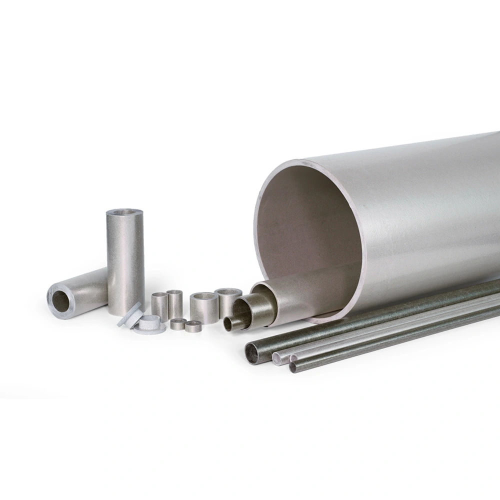
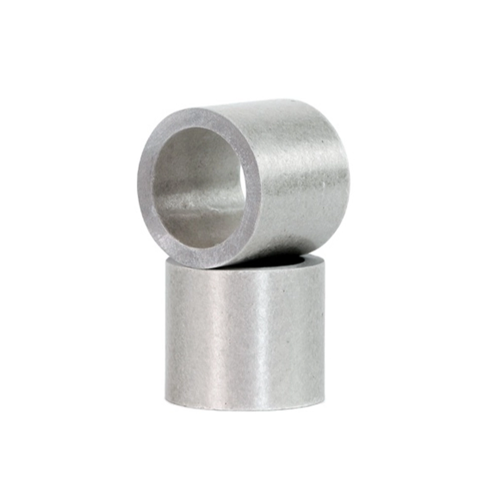
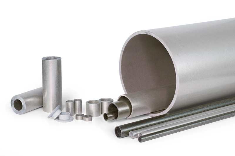
Customer-provided product-family photographs. Mineral grade, binder and reinforcement cannot be confirmed from appearance alone.
Phlogopite-based tubular insulation for components where heat exposure leads material selection.
• Phlogopite-based material route
• Rigid cylindrical insulating form
• Heat exposure defined at the component
• Electrical duty reviewed alongside temperature
• Wall, binder and mounting considered together
• Suitable enquiry route for heated sleeves and tubes
Define the heated tube
|
Feature |
Specify |
Assembly relationship |
|---|---|---|
|
Bore |
Member being surrounded and inner fit |
Position of the insulated component. |
|
Outer surface |
Outside envelope and contacts |
Clearance or contact with neighbouring parts. |
|
Wall |
Thickness relationship and construction |
Thermal and electrical role of the finished material. |
|
Length |
Insulating span and end positions |
Local conditions along the installed part. |
Thermal selection review
|
Question |
Review basis |
Do not assume |
|---|---|---|
|
Where does heat act? |
Component location and contact faces |
Equipment setting equals every wall temperature. |
|
How long is exposure? |
Sustained duty and separate heat events |
A peak is a continuous rating. |
|
What else must it do? |
Electrical separation and support |
Heat resistance proves electrical suitability. |
|
Which construction? |
Mineral, binder and finished form |
Raw mineral properties describe the complete tube. |
Understanding Phlogopite Mica Tubes
Phlogopite mica tubes offer a material-led route for tubular insulation near heat sources. They are considered where the thermal duty is a major part of the component’s function, while electrical separation and a defined cylindrical form are also needed. The selected tube must still be evaluated as a finished construction within the equipment.
Phlogopite is not the complete specification. Mica, bonding system, wall arrangement and finished geometry combine to make the usable product. A mineral-level description therefore cannot establish the service limit of every tube. The distinction is important when comparing a rigid tube with a flexible mica wrap or a different bonded component that performs another job.
This page separates the heat-led material choice from the form-led sleeve enquiry. A finished sleeve may use phlogopite construction, but its bore, length and end fit require their own definition. Treating those dimensions and operating conditions together provides a clearer basis for selection than assuming a higher-heat mineral automatically replaces an existing part.
Construction and Order Options
Define the bore around the insulated member and the outside envelope against the surrounding assembly. The wall must be consistent with those dimensions and the selected construction. Identify where the tube contacts another part and where clearance is intended, so its geometry reflects the actual heat and electrical arrangement rather than an isolated cylinder.
Length establishes the insulating span and the location of the tube ends. In heated equipment, those ends may lie in different local conditions from the middle section. The drawing should therefore show the installed position and relevant neighbouring parts, not only overall size. A longer tube is not automatically a solution to every exposure or mounting concern.
Describe sustained operation separately from temporary heat peaks. The temperature at the component may differ from the equipment setting, and the binder remains part of the finished material. When comparing options, retain electrical duty and mechanical support in the review rather than selecting solely by a published maximum-temperature statement.
Application Review
Heating-element arrangements may use a tube or sleeve to provide a cylindrical insulating boundary. The material review should identify where heat reaches the wall and how the part is supported. A proposed construction must be considered with the element and nearby components, not merely described as a heat-resistant tube.
Industrial heated assemblies can require insulation around a rod, terminal or other cylindrical member. Bore clearance and the insulating length are relevant to both fit and function. The part’s position within the equipment helps distinguish a material requirement from a claim about the performance of an entire furnace or machine.
Electrical equipment near hot zones may need thermal endurance without losing the focus on electrical separation. Review the conditions under which the finished tube must perform, including temperature at the part. A general phlogopite description is not a substitute for comparing relevant material information and evaluating the actual assembled component.
Handling, Fit and Inspection
A rigid phlogopite tube should be installed as a defined component, not bent or forced to accommodate an unsuitable fit. Review the bore, outside clearance and end arrangement before assembly. The material’s relevance to heat does not make it immune to damage introduced during handling or fitting around another part.
Inspect the finished surfaces and ends for visible cracks, edge damage or separation alongside dimensional checks. Pay attention to locations that support or position the tube, because an apparently minor defect may occur at a functional interface. Inspection should follow the component drawing and its role rather than a generic appearance checklist alone.
A trial component can connect fabrication, mounting and operating review. Consider the heated arrangement and electrical duty together, distinguishing the assessment of an individual tube from approval of the equipment. No borrowed supplier tolerance, certification or temperature value is presented here as a verified Normanson product rating.
When is phlogopite the useful starting point?
Phlogopite is a useful material family to evaluate when heat exposure is a leading requirement for a tubular insulating component. It is commonly considered alongside electrical separation rather than as a purely thermal material. The finished construction still matters: binder, wall arrangement and geometry all belong to the product being selected. Establish the conditions at the component, including whether heat is sustained or occurs in shorter events, before comparing candidate tubes. A higher-heat mineral description does not prove that a particular tube suits every hot installation. The material choice should be made around the actual assembly and its combined electrical, thermal and mechanical requirements.
Can its temperature capability be inferred from raw mica?
No. Raw mica is one constituent of a manufactured tube, not the complete product. The bonding system and finished construction must also remain suitable for the intended exposure. Published temperature statements may refer to different products, exposure durations or test conditions, so they should not be treated as interchangeable. Distinguish sustained operation from exceptional peaks and identify the temperature at the tube itself. A mineral comparison can help select a family for further evaluation, but it cannot establish an equipment rating. The appropriate assessment concerns the particular finished tube in its intended mounting and operating conditions, not the mineral in isolation. A comparison should therefore ask what was evaluated and for how long, rather than select the highest number attached to phlogopite. Where the information describes only a constituent, it can help explain the material family but does not fill the gap in evidence for the complete bonded tube and its intended installation.
What distinguishes this page from mica insulating sleeves?
This page begins with the mineral choice, while the sleeve page begins with the finished part’s fit and function. A phlogopite tube can be cut or specified as a sleeve around a cylindrical component, so the two descriptions may apply to the same item. They are not mutually exclusive grades. If heat-led material selection is the unresolved question, use the phlogopite route. If the material is already defined and the main task is bore, length or end geometry, the sleeve route is more direct. The final component description should combine both sets of information rather than use either name as a complete specification.
Why does the location inside heated equipment matter?
The component’s location helps define the heat exposure that the material actually experiences. Contact with a hot member, distance from a heated zone and the arrangement of surrounding parts can make the tube’s conditions different from a nominal equipment setting. Identify the relevant inner and outer surfaces and the positions of the ends before using a temperature statement in selection. Also explain whether the exposure is sustained or linked to an operating cycle. This keeps the review focused on the installed part. A tube that fits physically still requires appropriate electrical and thermal evaluation; its location is part of that assessment, not a minor detail added after material choice. A useful assembly view identifies which member is being insulated and where the tube meets other parts. That view helps connect the material choice with the real arrangement and makes differences between an existing and proposed component easier to recognise. The operating description should refer to that installed geometry.
Does a thicker wall automatically provide a better component?
Not automatically. Wall geometry changes the relationship between the bore and outside envelope, so increasing it can alter fit or available clearance. It also changes the physical arrangement being evaluated for insulation and support. Begin with the component’s required function and its installed geometry rather than selecting the largest wall by default. A material that is relevant to high heat still needs an appropriate binder and construction, and thickness does not remove those considerations. Compare candidate tubes as finished parts with the intended electrical duty, exposure and mounting. More material is not a substitute for confirming that the chosen geometry and construction suit the assembly.
What should be reviewed before approving a sample?
Review fit, material condition and the operating duty as separate but connected questions. Check the bore, outside envelope, length and end positions against the drawing, then inspect the functional surfaces for visible damage or separation. Evaluate how the part is supported and whether the installed position matches the intended thermal arrangement. If the tube provides electrical separation, that requirement should remain part of the assessment rather than be inferred from a successful fit check. A representative sample can reveal issues in geometry or handling, but visual acceptance alone does not establish equipment performance. Approval should relate to the selected construction and the actual conditions in which it will work.
Let Us Talk Now
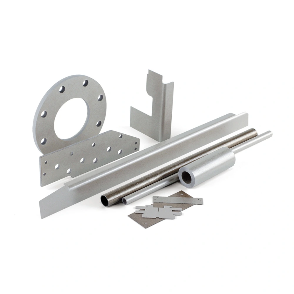
Share your material, dimensions, quantity and application. We will review the details with you.