
Muscovite Mica Tubes
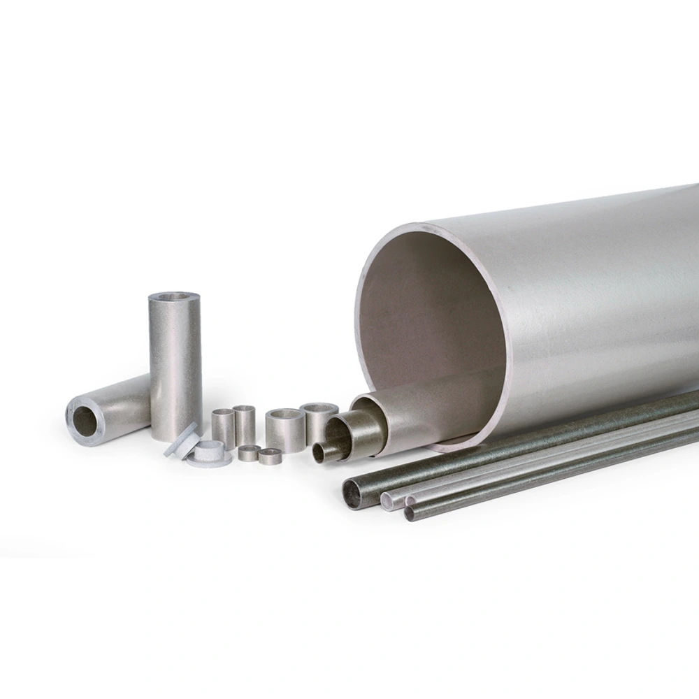
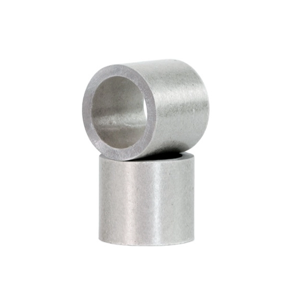
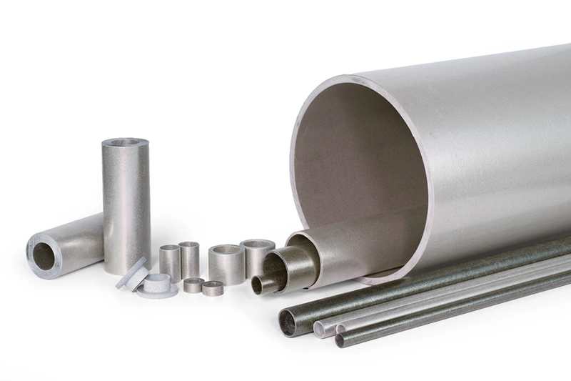
Customer-provided product-family photographs. Mineral grade, binder and reinforcement cannot be confirmed from appearance alone.
Rigid muscovite-based tubular insulation for electrically focused cylindrical components.
• Muscovite-based material route
• Rigid tubular component form
• Inside and outside fit considered together
• Wall and binder defined as a construction
• Relevant to rods, cores and heated assemblies
• Finished-part evaluation rather than mineral assumptions
Dimensional definition
|
Feature |
Define |
Review |
|---|---|---|
|
Bore |
Inside dimension and mating member |
Fit without assuming flexible conformity. |
|
Outside envelope |
Outer dimension and surrounding space |
Clearance and intended contact. |
|
Length |
Finished insulating span |
End locations in the assembly. |
|
Wall |
Relationship of bore and outer surface |
Consistency with the selected construction. |
Material and duty review
|
Topic |
Selection question |
Evidence needed |
|---|---|---|
|
Electrical role |
What does the tube separate? |
Component arrangement and relevant evaluation. |
|
Heat exposure |
Where and for how long is heat applied? |
Duty at the tube location. |
|
Construction |
Which mica and bonding system are intended? |
Finished-material description. |
|
Mechanical arrangement |
How is the part held? |
Drawing of supports and contacts. |
Understanding Muscovite Mica Tubes
Muscovite mica tubes provide a material-led route for selecting rigid tubular electrical insulation. The tube surrounds a cylindrical member or forms part of a defined insulating boundary in equipment. Its usefulness lies in combining the selected mica construction with the geometry needed by the assembly, rather than treating the mineral name as a complete component specification.
The construction includes a bonding system as well as mica. That matters because natural mica properties do not automatically describe every manufactured tube. Bore size, wall arrangement and length also influence how the part fits. A tube used as a finished sleeve remains a muscovite product if that is the selected mineral; sleeve and muscovite are not competing material categories.
This page focuses on electrically driven selection, including cylindrical insulation near heat. It does not imply that all muscovite tubes have one temperature or voltage rating. A useful comparison keeps the actual operating conditions attached to the finished construction and distinguishes a material result from approval of the complete equipment.
Construction and Order Options
Define the inside diameter around the member being insulated, then review the outside diameter against the surrounding space. Wall geometry connects those surfaces. A drawing should make clear which dimension controls fit and where contact is intended, so the tube is not described only by an overall nominal size that omits important assembly relationships.
Length and end positions establish the insulating span. Consider whether an end locates against another component, remains exposed or forms part of a larger stack. The same mineral can be relevant to different finished forms, but the geometry must follow the component’s role rather than assume that a longer or thicker tube automatically improves every aspect of insulation.
Binder and construction should be reviewed alongside heat exposure and mechanical conditions. Comparing an alternative tube means checking more than colour or diameter. Where thermal endurance becomes the dominant requirement, a phlogopite construction may warrant evaluation, but material substitution still needs to address the original electrical duty and mounting arrangement.
Application Review
Rod and terminal arrangements can use tubular insulation to separate a cylindrical conductive member from nearby equipment. The useful design information includes bore clearance, the required insulating length and the surrounding contact arrangement. A sleeve-shaped finished part is one possible form, not a separate mineral grade or a universal electrical rating.
Coil and core assemblies may use a tube to create a defined insulating boundary around a component. The selected construction should follow the actual mechanical and electrical role. Describing the core, support and end locations helps distinguish the finished-part requirement from a generic request for a cylinder of mica material.
Heated electrical assemblies can combine temperature exposure with an electrical separation requirement. Identify the conditions at the tube rather than only the heater’s setting. A muscovite route is a starting point for comparison; the binder, surrounding components and sustained or intermittent duty still determine whether the finished part is appropriate.
Handling, Fit and Inspection
Handle a tube as a manufactured insulating component with functional inner and outer surfaces. Avoid treating a rigid tube as a flexible wrap or using assembly force to compensate for an unsuitable bore. Before fitting, review the drawing and check that the identified contact and clearance surfaces correspond to the intended part.
Inspect the finished ends and visible construction for damage as well as checking fit. A crack, chipped edge or separation may matter at a locating or insulating surface even when the main dimensions appear correct. Inspection should be tied to the component’s function rather than limited to its general appearance.
A representative fitted component can help connect material choice with the actual arrangement. Dimensional fit, electrical suitability and thermal duty are separate questions that must remain coordinated. This page therefore uses specification questions and review conditions rather than borrowing another producer’s tolerances or laboratory values as guaranteed Normanson performance.
Why select a muscovite-based tube?
Muscovite provides a useful material route when electrical insulation is a leading requirement for a cylindrical component. That is a starting point for selection, not a complete performance guarantee. The finished tube also includes a bonding system and a particular wall arrangement, and its geometry determines how it fits into the equipment. Review the electrical duty, temperature at the part and mounting conditions together before choosing a construction. If heat exposure becomes the dominant issue, compare an appropriate phlogopite option without assuming automatic interchangeability. The relevant choice is the finished material that suits the actual component, rather than the mineral with the most attractive isolated property description.
Can a muscovite tube also be an insulating sleeve?
Yes. Muscovite identifies the mica constituent, while sleeve describes a finished part’s form or role around another component. A muscovite tube can therefore be specified as a sleeve with a defined bore, outside dimension and insulating length. The terms are not mutually exclusive and should not be treated as separate material grades. Use the mineral description to identify the intended construction and the sleeve drawing to explain the fit. This is particularly useful when replacing a short cylindrical part: a familiar sleeve name does not establish its binder, wall arrangement or operating suitability. Both material and geometry still need to appear in the component description.
Is bore size enough to specify the product?
No. The bore establishes only the inner fit. The outside dimension determines clearance or contact with surrounding parts, while length establishes the insulating span and the positions of the ends. Wall geometry connects the inner and outer surfaces, so it should remain consistent with both. A useful component drawing also identifies how the tube is supported and which features control installation. Without that context, two tubes with the same bore may serve different roles or fail to fit the same assembly. Specify the finished geometry as a coordinated set of requirements rather than assuming that one nominal diameter describes every important aspect of the insulating part. A drawing can clarify this by showing the insulated member, the tube and its neighbouring parts in the installed position. Marking functional fits separately from general dimensions helps avoid a comparison based only on an easy-to-measure diameter while the actual insulating and locating features remain unspecified.
Does the mineral determine the tube voltage rating?
The mineral alone does not establish a working-voltage rating for the finished tube or the equipment around it. Material test results describe specimens under stated conditions, while an assembled tube has particular ends, clearances, contact surfaces and operating temperatures. The bonding system and wall construction also belong to the product being evaluated. Use material information as an input to the electrical design, keeping its test conditions visible. Do not transfer a natural mica property or another tube supplier’s result directly to a new component. The relevant evidence should address the selected finished construction and the actual electrical separation required within the assembled equipment. The distinction is especially important when published information concerns natural mica or a different specimen shape. A tube presents an assembled cylindrical arrangement with ends and interfaces, so its intended use cannot be reduced to an isolated mineral property. Keep the relevant test and product descriptions together during the review.
What changes when the tube works close to a heater?
A heated location adds a thermal duty that must be considered alongside electrical separation and fit. Identify the temperature at the tube, its contact with surrounding parts and whether the exposure is sustained or occurs in shorter events. The heater’s nominal setting may not describe every surface of the insulating component. Review the binder and finished construction rather than relying only on the mineral’s general heat resistance. Mounting remains relevant because the part is still a rigid component within an assembly. A suitable room-temperature fit or electrical result is useful information, but neither one alone establishes that the tube is appropriate for the intended heated operating condition.
How should a replacement muscovite tube be compared?
Compare the existing part’s function, construction and geometry rather than relying only on its name. Record the bore, outside dimension, insulating length and end arrangement, then identify the electrical duty and heat exposure. If its bonding system or construction is known, keep that information attached to the comparison. A similar-looking tube may have a different intended role, and a dimensional match does not independently establish material equivalence. Review a representative finished component in the mounting arrangement and assess the relevant performance requirements. This separates the question of whether the replacement fits from the question of whether it provides the required insulation under the equipment’s actual conditions.
Let Us Talk Now
Share your material, dimensions, quantity and application. We will review the details with you.