
Machined Epoxy Insulation Parts
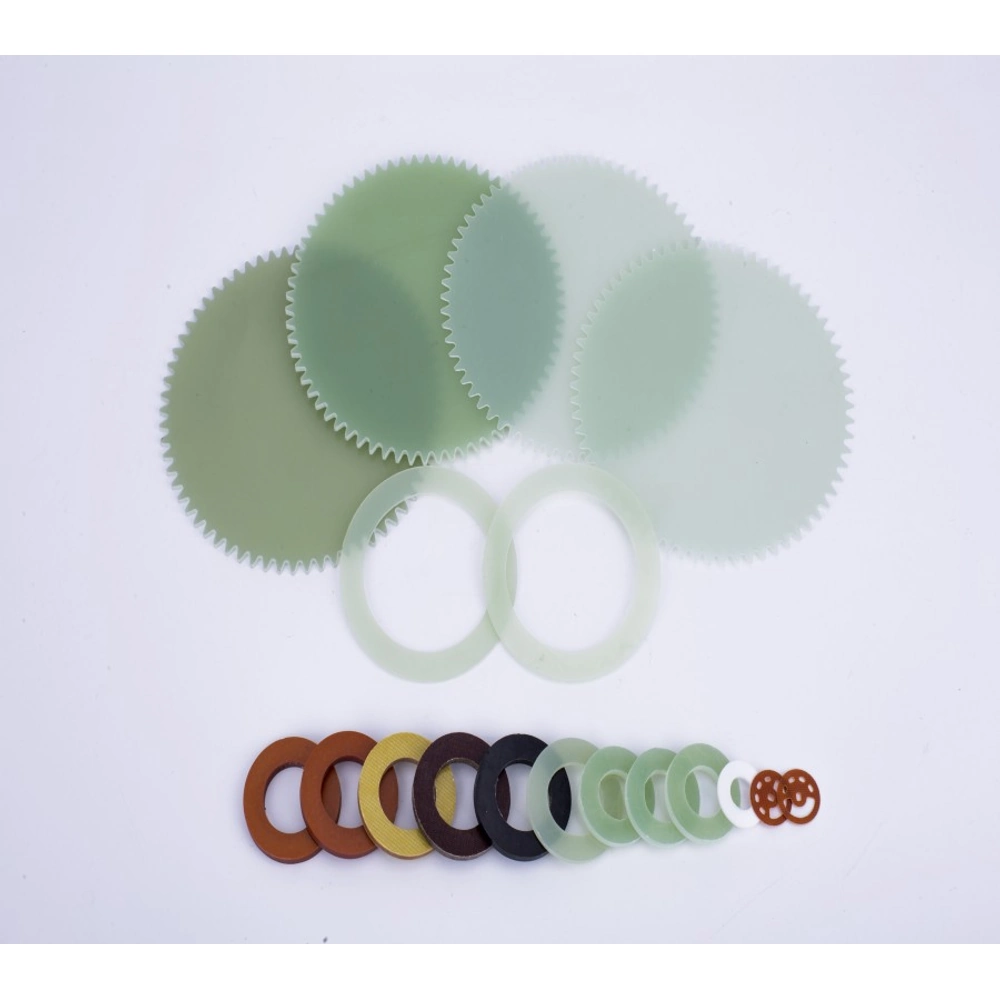
Supplier reference photograph of machined laminate profiles and mixed-material rings. Not a Normanson production photograph or confirmation of a stocked design.
Drawing-led enquiries for shaped glass-epoxy insulation components, with profiles, holes and contact faces reviewed against electrical and mechanical functions.
• Drawing-led component enquiries
• Profiles, apertures and mounting features
• Washers, spacers and shaped support concepts
• Functional surfaces identified before fabrication
• Material choice separated from geometry approval
• Project-specific inspection and documentation scope
Define the finished component
|
Feature group |
Include in the drawing |
Functional reason |
|---|---|---|
|
Outer profile |
Finished outline and relevant clearances |
Controls fit and separation from surrounding parts |
|
Holes and apertures |
Positions, sizes and feature relationships |
Locates fixings and preserves required sections |
|
Contact faces |
Locating and load-bearing surfaces |
Identifies the interfaces that govern assembly |
|
Recesses and steps |
Finished depth and remaining geometry |
Avoids evaluating only the original blank |
|
Material identity |
Required designation and any approved alternative |
Keeps geometry approval separate from material approval |
Machined-part acceptance review
|
Review item |
What it establishes |
What it does not establish |
|---|---|---|
|
Drawing revision |
The intended component definition |
Suitability of an unspecified material |
|
Material documentation |
The proposed construction and relevant evidence |
Automatic approval of every machined shape |
|
Dimensional inspection |
Agreement with specified geometry |
Complete equipment electrical performance |
|
Surface and edge review |
Visible condition at important interfaces |
All internal or long-term service properties |
|
Assembly evaluation |
Fit and function under the defined checks |
Unstated certification or universal application approval |
Understanding Machined Epoxy Insulation Parts
Machined epoxy insulation parts turn reinforced laminate forms into components with defined assembly interfaces. A finished part may combine a profile, mounting holes, recesses and contact faces that cannot be described adequately by the blank dimensions alone. The objective is not simply to reproduce an outline, but to preserve the required electrical separation while meeting the mechanical and locating functions of the design.
Glass-epoxy material selection and component geometry are related but separate decisions. A drawing can describe an accurate shape without identifying a suitable resin and reinforcement system. Equally, a documented laminate grade does not establish that a particular machined design is adequate for service. Review both together, including the effects of openings, reduced sections and the surfaces that actually contact other parts in the assembly.
This page is an enquiry route for drawing-based components rather than a declaration of fixed machining limits or stocked finished parts. The material, geometry and acceptance requirements are reviewed for the proposed project. Examples of washers, spacers and supports explain possible component forms; they do not imply that an illustrated design, certification or performance claim belongs to an existing Normanson production programme.
Construction and Order Options
Start from the final drawing and identify the features that control function. A profile may define clearance to nearby metalwork, while a hole pattern fixes the part to a support. Mark the locating faces and any surfaces that must remain uninterrupted. Separating these priorities from non-critical cosmetic details gives a clearer basis for considering the material form and proposed fabrication approach.
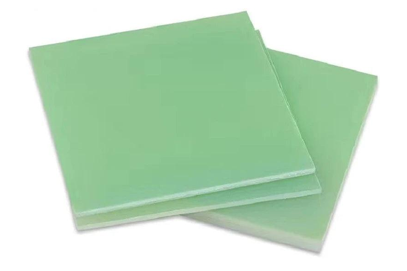
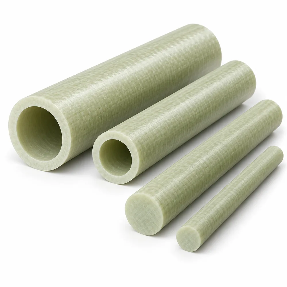
Choose the starting form with the finished component in mind. A flat laminate may suit a shaped plate or washer, while a cylindrical form may be more relevant to a sleeve or stepped spacer. Changing the route can change the reinforcement arrangement or material removed. Any alternative should therefore be compared against the actual drawing and duty, not accepted merely because its outside dimensions match.
Define what must be checked without assuming a universal tolerance or surface finish. Critical fits, hole relationships and working faces should be distinguished from general outline dimensions. If the drawing specifies a grade, maintain that identity through the enquiry and any revisions. Material equivalence, dimensional acceptance and appearance should remain separate review items so that approval of one does not silently approve the others.
Application Review
Mounting plates and insulating brackets combine attachment features with electrical separation. Review where forces enter the component and where conductive parts approach its edges or openings. The relevant geometry includes the remaining section after pockets and holes are made. A material selected for a plain panel should not automatically be assumed suitable for the same duty after substantial machining changes the load path.
Washers and spacers can maintain separation at bolted interfaces while establishing a defined contact distance. Their bore, outer profile, thickness and bearing faces all contribute to the assembly. Distinguish simple location from significant clamping duty, and consider the surrounding hardware. An insulating description alone does not establish a permitted installation load or guarantee the behaviour of a finished fastened joint.
Locating components and equipment fixtures may use machined holes, slots and shaped contact faces to position other parts. Where the fixture also provides insulation, contamination and unintended metal contact deserve attention alongside dimensional fit. Identify which faces perform the electrical and mechanical roles so that fabrication and inspection focus on the real interfaces instead of treating every visible surface as equally significant.
Handling, Fit and Inspection
Keep the drawing revision and material identity associated with the part throughout review and handling. Similar-looking components may differ in a hole location, recess depth or laminate requirement that is important in service. When a design changes, distinguish the new acceptance basis from the previous version rather than relying on an old sample alone. Traceable descriptions reduce ambiguity without implying any particular certification system.
The fabrication approach should suit glass-reinforced material and the remaining geometry. Holes near edges, narrow webs and interrupted surfaces require attention to support and the condition left after cutting. Glass-containing machining debris also requires appropriate workplace controls. This page does not prescribe tooling parameters or promise a process capability; the proposed method and results must meet the project’s agreed component requirements.
Before installation, compare the finished part with the correct drawing and review its functional surfaces, edges and openings. Resolve visible damage or uncertain material identification before the component enters an assembly. Where a trial fit or additional verification is required, define it as part of the acceptance plan. A visually neat part or a successful dimensional check does not by itself establish the full electrical performance of the equipment.
What information defines a machined epoxy insulation part?
The finished drawing should define the material requirement, geometry and features that determine the component’s function. Overall length, width or diameter is not enough when holes, pockets and contact faces control assembly fit. Identify the working surfaces, critical feature relationships and the correct drawing revision. Then consider the electrical separation and mechanical duty in the installed position. A sample can help explain appearance or a physical interface, but it should not silently replace missing design information. This page provides an enquiry route for that review; the final supply description and acceptance basis need to identify the actual component rather than a generic machined laminate part.
Can the same drawing be made from any epoxy glass material?
No. A drawing describes geometry, but its suitability also depends on the material construction and the service conditions. Visually similar glass-epoxy materials can differ in properties relevant to elevated temperature, flame requirements or mechanical duty. If a designation is already specified, keep it linked to the drawing during quotation and revision review. Any alternative requires an explicit comparison against the relevant requirements. Machining an identical outline from another laminate does not demonstrate equivalence. Likewise, a material with suitable published properties does not automatically validate every thin section or opening in the design. Material selection and finished-part assessment should remain coordinated but distinct decisions.
Which features deserve the most attention before machining?
Focus first on the features that locate, support or electrically separate the assembly. These may include contact faces, a mounting-hole pattern, a narrow section between openings or an edge close to conductive hardware. Identify their relationships on the drawing rather than assigning importance only by visual size. A small recess can be functionally significant if it changes the remaining insulating section. Non-critical cosmetic surfaces can then be distinguished from the interfaces that govern acceptance. This makes the review more precise without assuming a universal machining tolerance. The correct priorities come from the component’s role and surrounding assembly, not from a generic list of achievable features. Where several dimensions depend on the same locating face, show that relationship clearly. Checking each feature from a different reference can obscure whether they work together in the assembly. A clear drawing makes the intended comparison possible without inventing a tighter requirement for every surface.
Are insulating washers and spacers automatically suitable for clamping loads?
No automatic load suitability is implied by their shape or insulating material description. A washer or spacer may transfer force through small contact areas, and its behaviour depends on construction, geometry, temperature and the surrounding hardware. The bore, outer profile, thickness and bearing faces should therefore be considered together. Distinguish a part that mainly locates another component from one carrying substantial clamping duty. Installation requirements need to come from the actual equipment design and appropriate verification, not from an unrelated catalogue example. The enquiry should make that function clear so that the material and finished-part requirements are evaluated for the real joint.
How should finished machined parts be checked?
Use the correct drawing revision and separate dimensional checks from material and condition checks. Dimensions establish whether the part matches the defined geometry; material identification establishes what construction was proposed; inspection of edges and working faces helps identify visible damage or other unacceptable conditions. None of these alone proves the entire equipment’s electrical performance. Pay particular attention to the surfaces that contact or locate other parts and to openings that change the remaining section. If an assembly trial or additional test is required, define its purpose and acceptance basis explicitly. This avoids treating a neat appearance or successful trial fit as evidence for unrelated performance claims.
Can an old sample be used to reproduce a replacement component?
A sample can help establish shape and physical interfaces, but it should be treated as evidence to interpret rather than a complete specification. Wear, damage or previous modifications may obscure the intended dimensions, while appearance cannot reliably identify the original material. Compare the sample with available drawings, part records and the actual service function. Identify any assumptions before accepting a replacement design, especially for contact faces, holes and insulating paths. The agreed component definition should state the material and geometry being supplied. Reproducing an outline alone does not demonstrate that the replacement will have the same electrical, thermal or mechanical suitability as the original part. Keep observed dimensions separate from the intended design dimensions when the sample has visible wear. That distinction is particularly useful at bearing faces and fastening holes, where copying the current shape might reproduce damage rather than the original fit.
Let Us Talk Now
Share your material, dimensions, quantity and application. We will review the details with you.