
Epoxy Glass Laminate Sheets
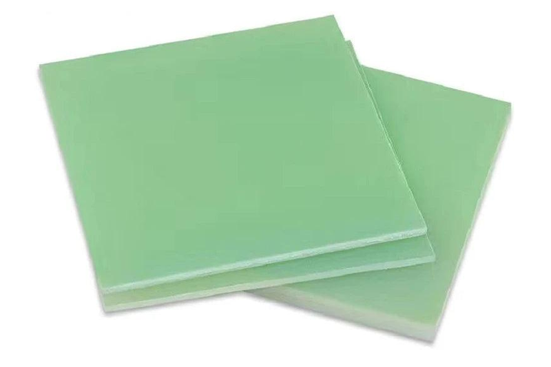
Supplier reference photograph of glass-epoxy sheet material. Not a Normanson production photograph or verified grade sample.
A flat-material enquiry route for electrical barriers, insulating panels and machined blanks. Compare the documented laminate construction with the finished component requirements.
• Flat panels and blanks as an enquiry format
• Glass reinforcement with an epoxy-based resin system
• Selection by documented material designation
• Review thickness and finished outline together
• Identify holes, contact faces and edge requirements
• Project-specific supply scope and verification
Sheet enquiry dimensions
|
Item |
Define in the enquiry |
Why it matters |
|---|---|---|
|
Thickness |
Required finished thickness and acceptance basis |
Affects fit and the remaining section after machining |
|
Outline |
Length, width and any non-rectangular profile |
Defines the component envelope and edge relationships |
|
Openings |
Hole, slot and aperture locations |
Connects fabrication to mounting and electrical paths |
|
Working faces |
Surfaces that locate or support the assembly |
Distinguishes functional requirements from appearance |
Material selection priorities
|
Priority |
Review |
Do not infer from |
|---|---|---|
|
Electrical insulation |
Applicable grade information and finished assembly |
Colour or thickness alone |
|
Mechanical support |
Load arrangement and relevant service conditions |
A single general strength statement |
|
Thermal duty |
Documented behaviour for the required exposure |
A temperature quoted for another laminate |
|
Flame requirements |
Required classification and supporting evidence |
The appearance of a similar panel |
|
Machined condition |
Edges, openings and contact surfaces |
An unmachined sheet photograph |
Understanding Epoxy Glass Laminate Sheets
Epoxy glass laminate sheets combine glass reinforcement and a cured resin system in a flat composite. They are considered for electrical barriers, terminal-support panels and other components that need insulation together with structural function. The material family is broad: the laminate designation, reinforcement and intended service conditions matter more than a shared colour or similar surface finish when selecting a sheet for a particular assembly.
The sheet may be the final panel, a cut blank or the starting material for a shaped component. That distinction changes what must be specified. A simple rectangular barrier needs a clear outline and thickness, whereas a mounting plate also depends on hole locations, edge distances and contact faces. Evaluate the finished geometry, including removed material, rather than relying only on the unmachined sheet description.
This page provides a structured enquiry route for epoxy glass sheets; it is not a statement that every grade or size is stocked. Common specification names can be discussed where relevant, but the proposed material and supply scope need project-specific confirmation. Technical comparisons here explain the questions to resolve and do not constitute a declared Normanson property table or equipment rating.
Construction and Order Options
A general electrical laminate, an elevated-temperature construction and a flame-retardant material are not simply different thickness options. They address different selection priorities. Preserve the grade named on an existing drawing and review any proposed replacement against its relevant requirements. Where no grade is established, begin with the electrical function, mechanical support conditions and thermal exposure instead of selecting the most familiar designation.
Define the difference between ordered blank dimensions and the dimensions required after fabrication. Overall length, width and thickness are only part of the description when the component has slots, apertures or countersunk fixings. Mark the surfaces that must remain continuous for insulation and the faces used for mounting. A drawing should make these priorities visible so that dimensional decisions are tied to function.
Choose the level of finishing that the assembly actually needs. A panel used as a broad barrier may not require the same surface or feature control as a locating plate. Conversely, an apparently minor recess can change the available insulating section. Any request for a particular edge treatment, surface condition or documentation should be considered with the material and finished-part requirements rather than assumed from a catalogue photograph.
Application Review
Electrical barriers use flat geometry to separate conductive areas or define a protected interface. The review should include mounting hardware, openings and the path around the panel edges. A thicker sheet does not independently prove that the arrangement is adequate. Use the equipment requirements to determine the necessary material evidence and assembly checks, especially where local heat or contamination may affect the installation.
Insulating support panels combine a mechanical role with electrical separation. The location of fixings and the area over which loads are transferred can be as important as the overall panel size. Consider whether the part is supported continuously or only at selected points. Keep the expected loading and heat exposure connected to the material comparison rather than evaluating either condition in isolation.
Machined blanks provide a route from sheet material to brackets, spacers and shaped insulating interfaces. Before removing material, identify the working surfaces and the dimensional relationships that determine assembly fit. Where multiple components come from the same drawing family, retain clear revision and material identification. This helps avoid mixing visually similar blanks that were selected for different functions or service conditions.
Handling, Fit and Inspection
Support sheets and blanks during handling so that corners, edges and exposed features are not unnecessarily damaged. Keep material identification associated with the pieces after cutting; appearance is not a reliable substitute for a grade record. Protect surfaces that will become electrical or mechanical interfaces from contamination and incidental marking. Storage and handling requirements should follow the specific supplied material documentation.
Glass-reinforced laminates require machining methods suited to an abrasive composite, not an assumption that ordinary plastic settings will produce an acceptable edge. The process review should address tooling, work support and safe control of machining debris. This page does not prescribe a cutting recipe. Judge the outcome against the drawing and material requirements, including holes and edges that become functional surfaces.
Inspect the finished panel before installation, checking material identity, dimensions and the condition of the relevant faces and edges. Look for visible damage or separation that could compromise the intended part, and resolve doubtful items before assembly. A dimensional check cannot demonstrate all electrical properties. Any required material evidence or application validation should remain part of the acceptance plan for the actual equipment.
What are epoxy glass laminate sheets used for?
They are commonly considered for flat electrical barriers, insulating support panels, terminal boards and blanks that will be machined into components. Their value comes from combining an insulating resin system with glass reinforcement, but a broad application name is not enough to select a specific sheet. A barrier and a loaded mounting panel can have quite different requirements even when they share the same outline. Identify what the finished part must separate, support or locate, then review its heat exposure and environment. The chosen construction and any required documentation should match that duty. This page describes an enquiry format rather than confirming a universal sheet specification.
How do I distinguish G10, G11 and FR4 when specifying a sheet?
Keep the designation attached to the requirements that led to its selection. These glass-epoxy families are often compared because they can look alike, but their specification priorities differ. General electrical and mechanical use, retention of properties at elevated temperature and flame-related behaviour should be examined separately. Do not replace a specified grade merely because another sheet is the same colour and thickness. Review the actual documentation for the proposed construction, including the particular property or classification required by the project. These names are discussed as technical selection categories; they do not establish that Normanson stocks or certifies every family mentioned on this page.
Is the thickest sheet always the safest option?
No. Thickness is one design variable, not a complete measure of safety or suitability. The component may also depend on the position of holes, the distance around an edge, mounting hardware and the way a load is applied. Increasing thickness can change fit or assembly relationships without resolving an unsuitable material choice. Start with the required geometry and identify the electrical and mechanical functions of the finished panel. Then evaluate the appropriate material and acceptance criteria. Where a recess or countersink removes part of the section, consider the remaining geometry rather than the original blank thickness. The equipment design determines the relevant assessment. Stacking thinner pieces is also a different arrangement from using one sheet: it introduces interfaces and may change how the component is supported or fastened. Treat such a change as a design decision that needs review, rather than an automatic way to reproduce a nominal total thickness.
Can a sheet be used as a finished panel without further machining?
A plain sheet or cut blank may serve as a panel when its dimensions, edges and surface condition meet the assembly requirements. It should not be assumed ready for installation solely because it is rectangular. Check whether the design requires mounting holes, controlled contact faces, protected edges or a particular outline. Also distinguish the condition of the supplied blank from the condition required in service. If no additional machining is intended, those finished-part requirements need to be clear in the enquiry. Inspect the actual item against the agreed description before use, and retain the relevant material identification rather than relying on visual similarity to a previous panel.
What should be checked around holes and machined edges?
Check both geometry and condition. Hole position and diameter may control assembly fit, while the material remaining between openings and edges can affect the component’s structural and insulating functions. Visible chipping, damage or separation should be assessed against the drawing and acceptance requirements rather than ignored because the main dimensions are correct. Identify surfaces that contact conductive parts or carry clamping force so that inspection focuses on the working interfaces. Machining glass-reinforced material requires an appropriate process and debris control. A clean-looking edge alone does not establish the electrical adequacy of the finished arrangement; that remains an assembly-level question. Where an opening is close to a fastener, consider whether the local contact and remaining section match the intended design.
Can a sheet photograph prove that it is suitable for my project?
No. A photograph can show general form and surface appearance, but it cannot reliably establish the reinforcement, resin system, material designation or required performance. Two panels may look similar while differing in properties important to heat exposure or flame behaviour. For an existing design, use its drawing and material record as the primary reference. For a new design, identify the component function and relevant service conditions before comparing documented options. Images are useful for discussing shape or visible defects, not for substituting one laminate for another. The agreed supply description and appropriate verification should determine acceptance of the actual sheet or finished panel.
Let Us Talk Now
Share your material, dimensions, quantity and application. We will review the details with you.