
Epoxy Glass Tubes & Rods
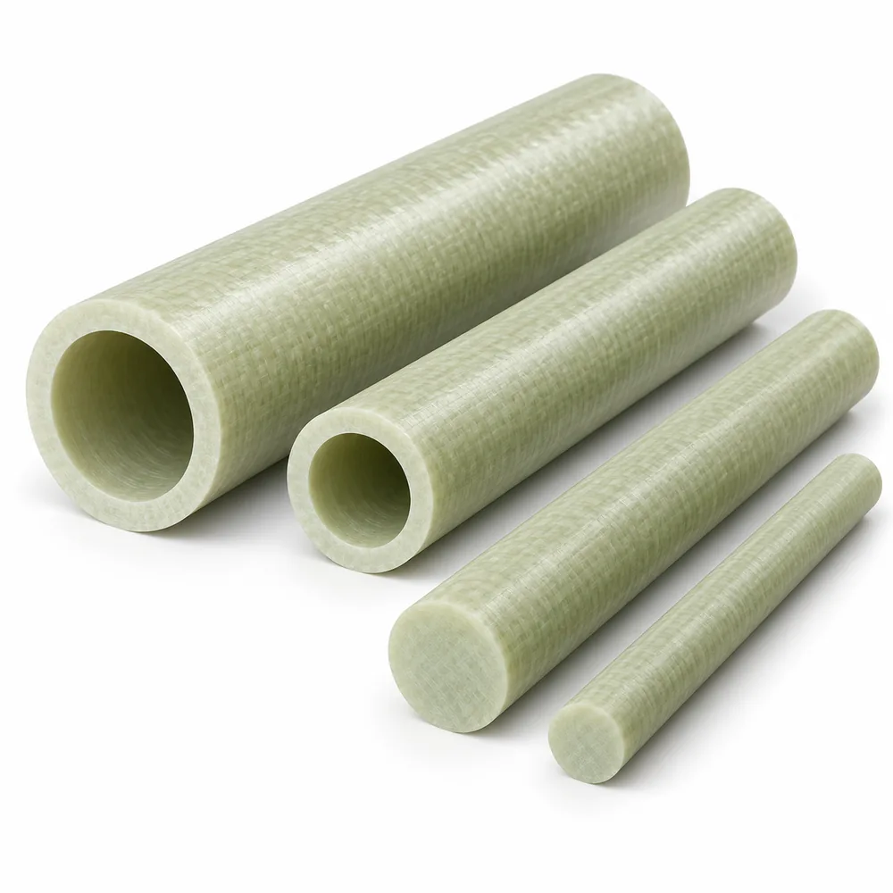
AI-generated illustration of generic glass-epoxy tubes and rods. This is not a product photograph, verified grade sample or dimensional specification.
Cylindrical insulation enquiries organised around bore, outside diameter, length and documented construction for sleeves, spacers and supporting components.
• Tube and solid-rod enquiry formats
• Bore and outside diameter reviewed separately
• Construction matched to the component function
• End faces and mounting interfaces identified
• Electrical, load and thermal conditions considered together
• Dimensions and supply scope confirmed by project
Define the cylindrical geometry
|
Feature |
Tube enquiry |
Rod enquiry |
|---|---|---|
|
Cross-section |
Bore and outside diameter |
Solid outside diameter and final profile |
|
Length |
Finished end-to-end requirement |
Blank length or finished component length |
|
Interfaces |
Bore, outer surface and contact ends |
Locating surface, shoulders and contact ends |
|
Added features |
Radial holes, slots or end machining |
Bores, recesses, steps or cross-holes |
|
Construction |
Documented tube reinforcement and resin |
Documented solid-form reinforcement and resin |
Cylindrical component selection
|
Question |
Why it matters |
Review basis |
|---|---|---|
|
Separation or structural support? |
Different functions place different demands on the part |
Assembly arrangement and load path |
|
What locates the component? |
Bore, outer surface and ends may each control fit |
Finished drawing and mating features |
|
Which construction is specified? |
Different reinforcement arrangements need not behave alike |
Material designation and supporting information |
|
Where is heat generated? |
Local exposure may differ from ambient conditions |
Actual service conditions |
|
Are fluid or pressure duties intended? |
An insulation tube is not automatically a qualified pressure component |
A separate project-specific suitability assessment |
Understanding Epoxy Glass Tubes & Rods
Epoxy glass tubes and rods provide cylindrical starting forms for insulating components. A tube has a bore surrounded by a reinforced wall, while a rod begins with a solid cross-section. These forms may be considered for sleeves, spacers and supporting elements in electrical equipment. Their usefulness depends on the documented construction and finished geometry, not simply on sharing the same external diameter or colour.
Tube construction deserves particular attention because glass reinforcement can be arranged through different manufacturing methods. Cloth-based laminated and filament-wound products are not automatically interchangeable. Reinforcement direction, resin system and the intended loading influence selection. A familiar tube designation should therefore stay connected to its material documentation, especially when the part must support an assembly while maintaining separation around a conductor or fastening element.
This page groups tube and rod enquiries without declaring a stock range or a universal performance specification. The required form, dimensions and any subsequent machining are considered for the project. Describing an application does not certify a component for that equipment. The enquiry should lead to an identified material construction and agreed acceptance requirements rather than assumptions based on an illustrative cylindrical product.
Construction and Order Options
Choose a tube when the bore is part of the functional geometry, for example where a sleeve surrounds another component. Define both internal and external requirements rather than specifying only wall thickness. The relationship between the bore, outer surface and end faces may determine fit. A tube chosen from its outside diameter alone can overlook the surfaces that actually locate or separate the assembly.
Choose a rod enquiry when a solid cylindrical blank is the appropriate starting point for the intended part. If a bore, shoulder or recess will be added, describe the finished component as well as the blank. Do not assume that drilling a rod produces the same construction or behaviour as a purpose-made tube. Compare the material route and the finished functional requirements before accepting an alternative.
Review the direction of loading and the role of the tube ends. A sleeve used mainly for separation differs from a spacer clamped between contact faces. End geometry, bore condition and any holes through the wall can change the assessment. Where flame behaviour or sustained heat exposure is relevant, evaluate the documented material requirement separately from the geometric choice of tube or rod.
Application Review
Insulating sleeves surround or separate a cylindrical component within an assembly. The review should cover the bore fit, outer interface, exposed ends and the resulting electrical paths. A convenient sliding fit does not by itself establish adequate insulation. Consider nearby metalwork and mounting details alongside the material construction so that the sleeve is assessed in the position where it will actually operate.
Spacers and stand-off components establish separation between connected parts. Their end faces may transfer clamping load, making length and contact geometry important as well as diameter. Avoid assuming that every insulating tube is also suitable as a structural spacer. The load arrangement, service temperature and remaining wall or section should be reviewed together before the form is incorporated into a design.
Cylindrical blanks may be machined into bushes, locating interfaces or other shaped insulation components. The starting form should leave the required geometry without obscuring its material identity. If the finished design includes steps, grooves or radial holes, identify those features early. The component should be evaluated by its final drawing and service conditions rather than by the nominal dimensions of the original blank.
Handling, Fit and Inspection
Protect tube ends, bores and rod surfaces during handling so that the faces used for fitting or electrical separation remain identifiable and undamaged. Support long items appropriately rather than using their ends as convenient lifting points. Keep the material designation and batch or item identification associated with cut sections. Similar-looking cylindrical pieces should not be mixed when their constructions or intended duties differ.
Cutting and machining should account for the reinforced construction and the features left in the finished part. Thin remaining walls, interrupted surfaces and drilled openings need suitable support during fabrication. The process must also address safe control of glass-containing machining debris. No generic cutting setting is prescribed here; the relevant objective is a component that meets the agreed geometry and surface-condition requirements.
Inspect the bore, outside geometry, length and working ends according to the drawing. Where the relationship between internal and external features controls assembly fit, define how that relationship will be checked rather than considering each diameter independently. Visible damage or separation needs review before installation. A dimensional pass does not replace any material evidence or electrical assessment required for the complete equipment assembly.
What is the main difference between a tube and a rod?
A tube has an internal bore; a rod starts as a solid cylindrical form. That geometric difference changes both the enquiry and the potential machining route. A sleeve normally needs a defined bore and outer interface, while a solid blank may later receive a shoulder, recess or hole. The material construction also matters: a drilled rod should not be treated as equivalent to a purpose-made tube without review. Identify the finished part and its function first, then compare the appropriate starting forms. This avoids selecting a blank that matches one convenient dimension but leaves the important fit, load or insulating requirements unresolved.
Why should the bore and outside diameter both be specified?
They define different surfaces that may perform different functions. The bore can locate around a conductor or fastener, while the outside surface fits another component or establishes separation from surrounding metalwork. Wall thickness describes the section between them but does not fully state those interfaces. End geometry and the relationship between internal and external features can also influence fit. For a functional sleeve, review the complete drawing rather than ordering by a single diameter. Where alignment matters, identify the required relationship and acceptance method. The electrical suitability of the assembled sleeve still needs its own assessment; a close dimensional fit is not proof of adequate insulation. Also distinguish dimensions required before machining from those needed on the completed sleeve. If a bore will be finished later, the enquiry should make that stage clear. Otherwise, a nominal blank dimension can be mistaken for an accepted finished interface, leaving the actual assembly requirement undefined.
Are cloth-laminated and filament-wound tubes the same?
No. Both can belong to the glass-epoxy family, but their reinforcement arrangements and manufacturing routes differ. That distinction can affect the properties relevant to a particular direction of loading or component duty. A similar colour, bore and outside diameter do not establish equivalence. Use the specified construction and its documentation when comparing alternatives, especially if the tube supports load as well as providing electrical separation. If the original drawing identifies only a broad material name, the functional conditions need closer review before a substitution is accepted. The suitable option is the one supported for the actual requirements, not simply the tube that resembles the existing part.
Can an insulating tube also be used as a clamped spacer?
It may be considered, but that duty requires review rather than being assumed from the word insulation. A clamped spacer transfers load through its ends and remaining section, so end condition, length and the surrounding assembly matter. Holes, grooves or a thin wall can change the component that is being evaluated. Consider the load arrangement together with temperature and the required electrical separation. The selected construction must be appropriate to that combined duty. Installation requirements should come from the equipment design, not from a generic tube description. Confirm the functional geometry and acceptance basis before treating a sleeve-style product as a structural spacer.
Are these tubes suitable for pressure or fluid service?
No pressure or fluid-service suitability is implied by this page. An epoxy glass tube described for electrical insulation is not automatically a qualified pipe, pressure vessel component or sealing interface. Such uses introduce separate questions about the material construction, loads, fluids, joints and validation of the complete system. Even a tube with a visually continuous wall may have been specified for a very different duty. If the intended component will contain fluid or carry pressure, that requirement needs an explicit technical assessment and appropriate evidence. Do not infer a pressure rating from dimensions, resin type or examples of unrelated applications elsewhere in the glass-epoxy product family. A general statement about resistance to a liquid is not equivalent to a validated containment application. The condition of the ends and any connections also belongs to the system assessment, so a material comparison by itself cannot approve the proposed use.
What should be inspected after cutting or machining a tube?
Check the finished length, bore, external geometry and the faces that contact the assembly. Inspect visible edges and openings for damage or separation, and assess any doubtful condition against the drawing and material requirements before installation. If concentric relationships or end alignment determine fit, those relationships need an agreed checking method rather than separate diameter measurements alone. Retain identification when a longer item is divided into shorter pieces so that construction records are not lost. Dimensional inspection establishes whether the component matches the specified geometry; it does not independently prove its electrical or thermal suitability. Those questions remain tied to the material evidence and intended equipment duty.
Let Us Talk Now
Share your material, dimensions, quantity and application. We will review the details with you.